- 您现在的位置:买卖IC网 > PDF目录64885 > FA7622CP 0.6 A DUAL SWITCHING CONTROLLER, 1000 kHz SWITCHING FREQ-MAX, PDIP20 PDF资料下载
参数资料
| 型号: | FA7622CP |
| 元件分类: | 稳压器 |
| 英文描述: | 0.6 A DUAL SWITCHING CONTROLLER, 1000 kHz SWITCHING FREQ-MAX, PDIP20 |
| 封装: | DIP-20 |
| 文件页数: | 5/8页 |
| 文件大小: | 67K |
| 代理商: | FA7622CP |
FA7622CP(E)
5
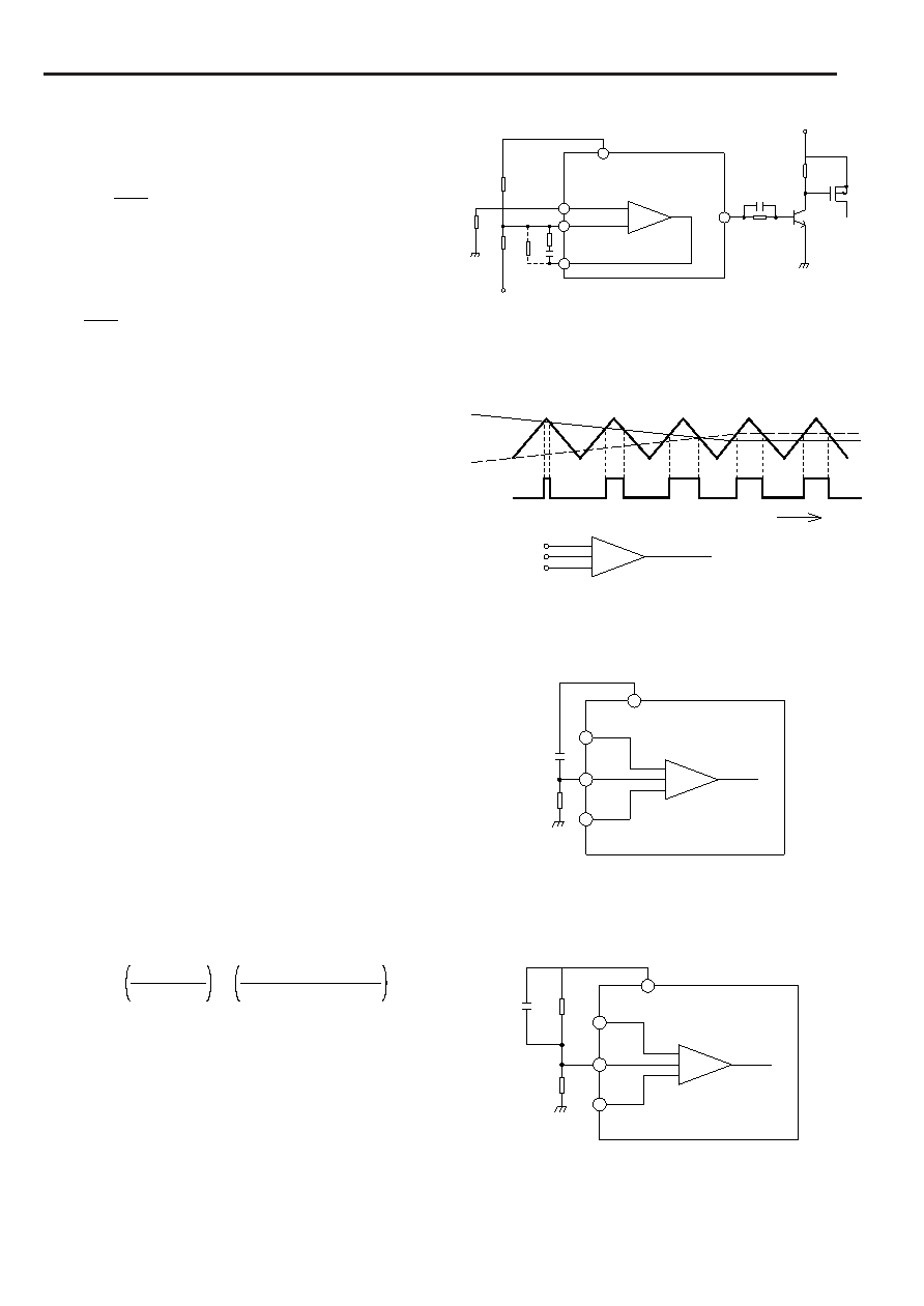
Inverting chopper circuit
According to the circuit shown in Fig. 5, the power output
voltage VOUTB can be determined as follows:
VOUTB = –
R11
R10
(5)
..............................
VREF
The AV between the VOUTB and FB2 pins can be determined
as follows:
AV
–R11
R12
(6)
.................................................
To correct the phase, connect the resistor R13 and capacitor
C3 in series between the IN2– and FB2 pins.
By using this circuit, invert the output polarity of OUT2 with an
external transistor to drive a P-channel MOSFET (or PNP
transistor).
3. PWM comparator section
As Fig. 6 shows, a PWM comparator has three input
terminals. PWM comparator 1 determines the duty cycle of
the output from the OUT1 pin. This comparator compares the
CT oscillator Voltage (Pin 1) with the FB1 voltage (Pin 17) or
the DT1 voltage (Pin 16), whichever is greater. When the
highest of these voltages is lower than the CT voltage, the
PWM output is high. When it is higher than CT, the PWM
output is low.
PWM comparator 2 determines the duty cycle of the output
from the OUT2 pin. To determine the PWM output, this
comparator compares the CT oscillator voltage (Pin 1) with the
FB2 voltage (Pin 6) or the DT2 voltage (Pin 7) whichever is
higher.
During ordinary operation, the OUT1 and OUT2 pin voltages
have the same polarity as the output from each comparator.
When the power supply is turned on, the pulse width
gradually increases. The time constant for soft-start is
determined by the external resistor and capacitor across pins
16 and 7. In Figures 7 and 8, the time ts required for the pulse
width (duty-cycle) to reach about 30% after start-up can be
determined as follows:
(Units:
F for Cs and k for Rs, Rs1, and Rs2)
Fig. 5
Fig. 8
Fig. 6
C3
Q3
FB2
R10
R9
REF
R11
R12
R13
IN2
ER.AMP2
VCC1
+
-
V OUTB (Controlled by Q3)
10
20
6
5
4
OUT2
PWM output
FB1(FB2)
DT1(DT2)
Time
CT
PWM output
PWM1
(PWM2)
DT1(DT2)
FB1(FB2)
CT
Fig. 7
DT1(DT2)
20
1
FB1(FB2)
CS
CT
RS
REF
PWM output
PWM1
(PWM2)
20
1
DT1(DT2)
FB1(FB2)
CS
CT
RS2
REF
PWM output
PWM1
(PWM2)
RS1
Fig.8:
tS (mS) = CS
ln
RS1
0.417RS1 – 0.583 RS2
(7)
.................................
Fig.7:
tS (mS) = 0.54CS RS
Where, RS1
/ RS2 > 0.716
(8)
……
RS1 RS2
RS1
RS2
Please connect enough large capacitance between REF and
GND pins in order to prevent irregular output pulse caused by
minus voltage at DT1 or DT2 pin when IC is shut down.
相关PDF资料 |
PDF描述 |
|---|---|
| FA7622M | 0.6 A DUAL SWITCHING CONTROLLER, 1000 kHz SWITCHING FREQ-MAX, PDSO20 |
| FA7622P | 0.6 A DUAL SWITCHING CONTROLLER, 1000 kHz SWITCHING FREQ-MAX, PDIP20 |
| FA7630CE | 0.5 A DUAL SWITCHING CONTROLLER, 500 kHz SWITCHING FREQ-MAX, PDSO20 |
| FA7630CP | 0.5 A DUAL SWITCHING CONTROLLER, 500 kHz SWITCHING FREQ-MAX, PDIP20 |
| FA7630CE | 0.5 A DUAL SWITCHING CONTROLLER, 500 kHz SWITCHING FREQ-MAX, PDSO20 |
相关代理商/技术参数 |
参数描述 |
|---|---|
| FA7622CPE | 制造商:FUJI 制造商全称:Fuji Electric 功能描述:Bipolar IC For Switching Power Supply Control |
| FA7622P | 制造商:未知厂家 制造商全称:未知厂家 功能描述: |
| FA7630CE | 制造商:未知厂家 制造商全称:未知厂家 功能描述:Analog IC |
| FA7630CP | 制造商:FUJI 制造商全称:Fuji Electric 功能描述:Bipolar IC For Switching Power Supply Control |
| FA7630CPE | 制造商:FUJI 制造商全称:Fuji Electric 功能描述:Bipolar IC For Switching Power Supply Control |
发布紧急采购,3分钟左右您将得到回复。