- 您现在的位置:买卖IC网 > Datasheet目录38 > FAN4800AUN (Fairchild Semiconductor)IC PWM/PFC CTLR COMBO 16-MDIP Datasheet资料下载
参数资料
| 型号: | FAN4800AUN |
| 厂商: | Fairchild Semiconductor |
| 文件页数: | 13/19页 |
| 文件大小: | 1414K |
| 描述: | IC PWM/PFC CTLR COMBO 16-MDIP |
| 标准包装: | 1,800 |
| 模式: | 平均电流 |
| 频率 - 开关: | 240kHz ~ 268kHz |
| 电流 - 启动: | 30µA |
| 电源电压: | 11 V ~ 22 V |
| 工作温度: | -40°C ~ 105°C |
| 安装类型: | 通孔 |
| 封装/外壳: | 16-DIP(0.300",7.62mm) |
| 供应商设备封装: | 16-MDIP |
| 包装: | 管件 |
?2011 Fairchild Semiconductor Corporation
www.fairchildsemi.com
FAN4800AU/CU " Rev. 1.0.1
13
Functional Description
Oscillator
The internal oscillator frequency is determined by the
timing resistor and capacitor on the RT/CT pins as
shown in Figure 25. The frequency of the internal
oscillator is given:
T
T
T
O SC
C
C
R
360
56
.
0
1
+
?/DIV>
?/DIV>
=
(1)
Because the PWM stage generally uses a forward
converter, it is necessary to limit the maximum duty
cycle at 50%. To have a small tolerance of the
maximum duty cycle, a frequency divider with toggle
flip-flops is used, as illustrated in Figure 25. The
operation frequency of PFC and PWM stage is 1/4 of
oscillator frequency. (For FAN4800CU, the operation
frequencies for PFC and PWM stages are 1/4 and 1/2
of oscillator frequency, respectively).
The dead time for the PFC gate drive signal is
determined by:
T
D E A D
C
3 6 0
=
(2)
The dead time should be smaller than 2% of the
switching period to minimize line current distortion
around the line zero crossing.
RT /C T
V
RE F
O S C
T Q
T -F F
T
Q
O P W M (F A N 4 8 0 0 C U )
O P F C , O P W M
T -F F
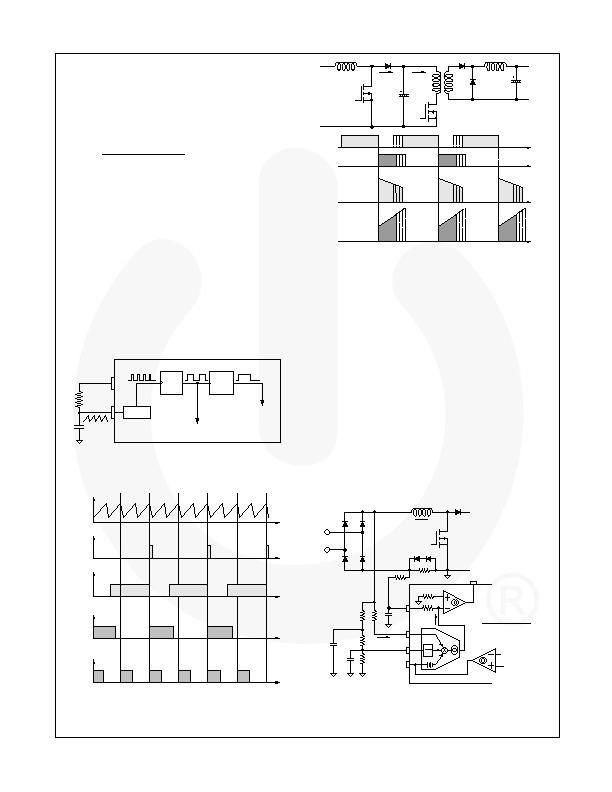
Figure 25. Oscillator Configuration
R T / C T
O P F C
O P W M
O P W M ( F A N 4 8 0 0 C U )
P F C D e a d - T i m e
Figure 26. Timing Diagram
I
D
I
D S
V
G . P F C
V
G .P W M
V
G . P F C
V
G . P W M
I
D S
I
D
Figure 27. Interleaved Leading / Trailing
Edge Modulation
Figure 27 shows the interleaved leading / trailing edge
modulation, where the turn-off of the PFC drive signal is
synchronized to the turn-on of the PWM drive signal.
This technique allows the PFC output diode current to
flow directly into the downstream DC/DC converter,
minimizing the current ripple of PFC output capacitor.
Gain Modulator
Gain modulator is the key block for the PFC stage
because it provides the reference to the current control
error amplifier for the input current shaping, as shown in
Figure 28. The output current of the gain modulator is a
function of V
EA
, I
AC,
and V
RMS
. The gain of the gain
modulator is given as a ratio between I
MO
and I
AC
with a
given V
RMS
when V
EA
is saturated to HIGH. The gain is
inversely proportional to V
RMS
2
, as shown in Figure 29,
to implement line feed-forward. This automatically
adjusts the reference of current control error amplifier
according to the line voltage, such that the input power
of PFC converter is not changed with line voltage (as
shown in Figure 30).
IS E N S E
IA C
V R M S
V E A
=
?/DIV>
?nbsp -
= ?/DIV>
-
2
( 0
. 6
)
.
M O A
C
E
A
A
C
M
A
X
G
I
K
V
I
V V
IE A
R M
R
M
G a in
M o d u la to r
R R M S 1
R R M S 2
R
R M S 3
C R M S 1
C
R M S 2
R
I A C
I A C
V
I N
I
L
x
2
k
Figure 28. Gain Modulator Block
相关PDF资料 |
PDF描述 |
|---|---|
| FAN4800CUN | IC PWM/PFC CTLR COMBO 16-MDIP |
| FAN4802MY | IC PFC CTRLR AVERAGE CURR 16SOP |
| FAN4802SNY | IC CTLR PFC/PWM COMBO 16-PDIP |
| FAN6920MRMY | IC PWM CTLR PFC/QUASI-RES 16SOP |
| FAN6921MLMY | IC CTLR PFC/FLYBACK 16-SOICN |
相关代理商/技术参数 |
参数描述 |
|---|---|
| FAN4800C | 制造商:FAIRCHILD 制造商全称:Fairchild Semiconductor 功能描述:PFC/PWM Controller Combination |
| FAN4800CMY | 功能描述:电流型 PWM 控制器 PWM/PFC, Avg Curr 30uA SU, 2.6mA Op RoHS:否 制造商:Texas Instruments 开关频率:27 KHz 上升时间: 下降时间: 工作电源电压:6 V to 15 V 工作电源电流:1.5 mA 输出端数量:1 最大工作温度:+ 105 C 安装风格:SMD/SMT 封装 / 箱体:TSSOP-14 |
| FAN4800CNY | 功能描述:电流型 PWM 控制器 PWM/PFC, Avg Curr 30uA SU, 2.6mA Op RoHS:否 制造商:Texas Instruments 开关频率:27 KHz 上升时间: 下降时间: 工作电源电压:6 V to 15 V 工作电源电流:1.5 mA 输出端数量:1 最大工作温度:+ 105 C 安装风格:SMD/SMT 封装 / 箱体:TSSOP-14 |
| FAN4800CS | 制造商:FAIRCHILD 制造商全称:Fairchild Semiconductor 功能描述:PFC/PWM Controller Combination |
| FAN4800CSMY | 功能描述:电流型 PWM 控制器 PFC/PWM Controller Combination RoHS:否 制造商:Texas Instruments 开关频率:27 KHz 上升时间: 下降时间: 工作电源电压:6 V to 15 V 工作电源电流:1.5 mA 输出端数量:1 最大工作温度:+ 105 C 安装风格:SMD/SMT 封装 / 箱体:TSSOP-14 |
发布紧急采购,3分钟左右您将得到回复。