- 您现在的位置:买卖IC网 > PDF目录370147 > FAN5242QSC PDF资料下载
参数资料
| 型号: | FAN5242QSC |
| 文件页数: | 16/20页 |
| 文件大小: | 123K |
| 代理商: | FAN5242QSC |
FAN5201
16
P
Non-Supported Communications
The following features are specified in the Intel/Duracell
Smart Charger Specification, but are not directly supported
by the FAN5201.
Thermistor Interface
Interface to the thermistor occurs exclusively through the host.
Typical Battery Communications
Charging current and voltage requests are intercepted by the
host, which transmits them to the charger.
Critical Battery Communications
Overcharge and overtemperature communications are sent to
the host, which transmits commands to the charger.
Bus Errors
Unsupported commands, data unavailable, busy or bad data
are not transmitted to the host. The FAN5201 signals errors
by witholding ACKnowledge (see protocols). It does not
support any reads of error registers.
AlarmWarnings()
Alarm warnings are sent to the host, which transmits com-
mands to the charger.
Chargermode() Settings
The ChargerMode() write command is unsupported. The
command’s effects may be obtained by sending the appropri-
ate commands to the charger.
175 seconds Timeout
Supported by the host, not by the IC. Furthermore, it is rec-
ommended that a watchdog timer be used in conjunction
with the host processor, to assure that the timeout is not
affected by infinite software loops.
Table 7. Charger Settings Read
Field
Byte Count
Charger Current Low Byte
Charger Current High Byte
Charger Voltage Low Byte
Charger Voltage High Byte
Charger Power Low Byte
Charger Power High Byte
Control Signal Low Byte
Control Signal High Byte
Byte
Always set to 0x08
1
2
3
4
5
6
7
8
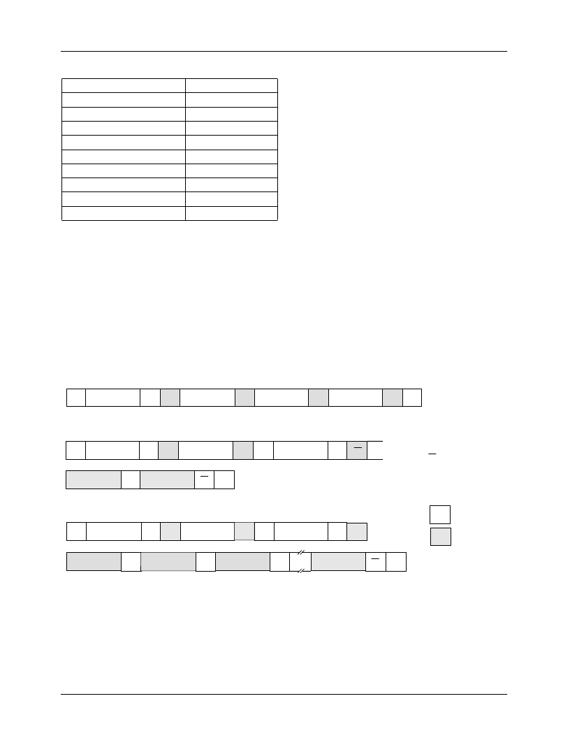
Figure 12. Read and Write Protocols
S
Slave Address
Slave Address
Slave Address
Slave Address
Slave Address
Wr
Wr
A
Command Code
Command Code
Command Code
A
Data Byte Low
Data Byte High
Data Byte Low
Data Byte High
P
Write Word Protocol
S
S
Rd
…
A
P
Read Word Protocol
S
Wr
A
A
S
Rd
A
Byte Count = N
A
Data Byte 1
Data Byte 2
Data Byte N
A
A
A
P
Block Read Protocol
Master to Slave
Slave to Master
A
A
A
A
A
A
S = StartCondition
Wr = Write
Rd = Read
A = Acknowledge
A = Not Acknowledge
P = Stop Condition
相关PDF资料 |
PDF描述 |
|---|---|
| FAN5242QSCX | |
| FAN5201 | |
| FAN8005D2TF | Servo Motor Controller/Driver |
| FAN8007D | Servo/Spindle Motor Controller/Driver |
| FAN8007DTF | Servo/Spindle Motor Controller/Driver |
相关代理商/技术参数 |
参数描述 |
|---|---|
| FAN5242QSCX | 功能描述:开关变换器、稳压器与控制器 PWM Controller RoHS:否 制造商:Texas Instruments 输出电压:1.2 V to 10 V 输出电流:300 mA 输出功率: 输入电压:3 V to 17 V 开关频率:1 MHz 工作温度范围: 安装风格:SMD/SMT 封装 / 箱体:WSON-8 封装:Reel |
| FAN5250 | 制造商:FAIRCHILD 制造商全称:Fairchild Semiconductor 功能描述:Mobile Processor Core-Voltage Regulator |
| FAN5250_ADB3026B WAF | 制造商:Fairchild Semiconductor Corporation 功能描述: |
| FAN5250_AZB3026B WAF | 制造商:Fairchild Semiconductor Corporation 功能描述: |
| FAN5250QSC | 功能描述:DC/DC 开关控制器 DC/DC RoHS:否 制造商:Texas Instruments 输入电压:6 V to 100 V 开关频率: 输出电压:1.215 V to 80 V 输出电流:3.5 A 输出端数量:1 最大工作温度:+ 125 C 安装风格: 封装 / 箱体:CPAK |
发布紧急采购,3分钟左右您将得到回复。