- 您现在的位置:买卖IC网 > PDF目录370147 > FAN8005D2 Servo Motor Controller/Driver PDF资料下载
参数资料
| 型号: | FAN8005D2 |
| 英文描述: | Servo Motor Controller/Driver |
| 中文描述: | 伺服电机控制器/驱动器 |
| 文件页数: | 37/191页 |
| 文件大小: | 2018K |
| 代理商: | FAN8005D2 |
第1页第2页第3页第4页第5页第6页第7页第8页第9页第10页第11页第12页第13页第14页第15页第16页第17页第18页第19页第20页第21页第22页第23页第24页第25页第26页第27页第28页第29页第30页第31页第32页第33页第34页第35页第36页当前第37页第38页第39页第40页第41页第42页第43页第44页第45页第46页第47页第48页第49页第50页第51页第52页第53页第54页第55页第56页第57页第58页第59页第60页第61页第62页第63页第64页第65页第66页第67页第68页第69页第70页第71页第72页第73页第74页第75页第76页第77页第78页第79页第80页第81页第82页第83页第84页第85页第86页第87页第88页第89页第90页第91页第92页第93页第94页第95页第96页第97页第98页第99页第100页第101页第102页第103页第104页第105页第106页第107页第108页第109页第110页第111页第112页第113页第114页第115页第116页第117页第118页第119页第120页第121页第122页第123页第124页第125页第126页第127页第128页第129页第130页第131页第132页第133页第134页第135页第136页第137页第138页第139页第140页第141页第142页第143页第144页第145页第146页第147页第148页第149页第150页第151页第152页第153页第154页第155页第156页第157页第158页第159页第160页第161页第162页第163页第164页第165页第166页第167页第168页第169页第170页第171页第172页第173页第174页第175页第176页第177页第178页第179页第180页第181页第182页第183页第184页第185页第186页第187页第188页第189页第190页第191页
FAN1582
PRODUCT SPECIFICATION
6
P
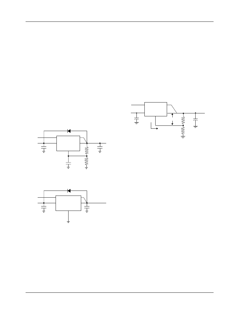
A protection diode between the input and output pins is usu-
ally not needed. An internal diode between the input and the
output pins on the FAN1582 series can handle microsecond
surge currents of 50A to 100A. Even with large value output
capacitors it is difficult to obtain those values of surge cur-
rents in normal operation. Only with large values of output
capacitance, such as 1000μF to 5000μF, and with the input
pin instantaneously shorted to ground can damage occur. A
crowbar circuit at the input can generate those levels of current;
a diode from output to input is then recommended, as shown
in Figure 1. Usually, normal power supply cycling or system
“hot plugging and unplugging” will not generate current
large enough to do any damage.
The adjust pin can be driven on a transient basis ±7V with
respect to the output, without any device degradation. As with
any IC regulator, exceeding the maximum input-to-output
voltage differential causes the internal transistors to break
down and none of the protection circuitry is then functional.
Figure 1. Optional Protection Diode
Ripple Rejection
In applications that require improved ripple rejection, a bypass
capacitor from the adjust pin of the FAN1582 to ground
reduces the output ripple by the ratio of V
OUT
/1.25V. The
impedance of the adjust pin capacitor at the ripple frequency
should be less than the value of R1 (typically in the range of
100
to 120
) in the feedback divider network in Figure 1.
Therefore, the value of the required adjust pin capacitor is a
function of the input ripple frequency. For example, if R1 equals
100
and the ripple frequency equals 120Hz, the adjust pin
capacitor should be 22μF. At 10kHz, only 0.22μF is needed.
Output Voltage
The FAN1582 regulator develops a 1.25V reference voltage
between the output pin and the adjust pin (see Figure 2).
Placing a resistor R1 between these two terminals causes a
constant current to flow through R1 and down through R2 to
set the overall output voltage. Normally, this current is the
specified minimum load current of 10mA.
The current out of the adjust pin adds to the current from R1
and is typically 35μA. Its output voltage contribution is small
and only needs consideration when a very precise output
voltage setting is required.
Figure 2. Basic Regulator Circuit
Load Regulation
The FAN1582 family provides true remote sensing, eliminat-
ing output voltage errors due to trace resistance. To utilize
remote sensing, connect the VSENSE pin directly to the
load, rather than at the VOUT pin. If the load is more than 1"
away from the FAN1582, it may be necessary to increase the
load capacitance to ensure stability.
Thermal Considerations
The FAN1582 series protect themselves under overload con-
ditions with internal power and thermal limiting circuitry.
However, for normal continuous load conditions, do not exceed
maximum junction temperature ratings. It is important to
consider all sources of thermal resistance from junction-to-
ambient. These sources include the junction-to-case resistance,
the case-to-heat sink interface resistance, and the heat sink
resistance. Thermal resistance specifications have been
developed to more accurately reflect device temperature and
ensure safe operating temperatures. The electrical character-
istics section provides a separate thermal resistance and
maximum junction temperature for both the control circuitry
and the power transistor. Calculate the maximum junction
temperature for both sections to ensure that both thermal
limits are met.
For example, look at using an FAN1582T-1.5 to generate 3A
@ 1.5V ± 2% from a 3.3V source (3.2V to 3.6V).
FAN1582
Adj
Vin
C2
22
μ
F
V
OUT
+
C1
10
μ
F
+
C
ADJ
+
Vcntl
Vsense
Vout
R1
R2
D1
1N4002
(OPTIONAL)
V
IN
V
OUT
FAN1582–1.5, 2.5
Gnd
Vin
C2
22
μ
F
V
OUT
+
C1
10
μ
F
+
Vcntl
Vsense
Vout
D1
1N4002
(OPTIONAL)
V
IN
V
CNTL
C2
22
μ
F
V
IN
V
OUT
V
REF
C1
10
μ
F
V
cntl
+
+
Vcntl
Vsense
Vin
Adj
Vout
FAN1582
R1
R2
I
ADJ
50
μ
A
V
OUT
= V
REF
(1+R2/R1) + I
ADJ
(R2)
相关PDF资料 |
PDF描述 |
|---|---|
| FAN8035L | MOTOR CONTROLLER |
| FAN8039D3 | Servo/Spindle Motor Controller/Driver |
| FAN8800 | |
| FAN6555M | SMPS Controller |
| FAN6555MX | SMPS Controller |
相关代理商/技术参数 |
参数描述 |
|---|---|
| FAN8005D2TF | 制造商:未知厂家 制造商全称:未知厂家 功能描述:Servo Motor Controller/Driver |
| FAN8006D3 | 功能描述:马达/运动/点火控制器和驱动器 RoHS:否 制造商:STMicroelectronics 产品:Stepper Motor Controllers / Drivers 类型:2 Phase Stepper Motor Driver 工作电源电压:8 V to 45 V 电源电流:0.5 mA 工作温度:- 25 C to + 125 C 安装风格:SMD/SMT 封装 / 箱体:HTSSOP-28 封装:Tube |
| FAN8006D3TF | 功能描述:马达/运动/点火控制器和驱动器 RoHS:否 制造商:STMicroelectronics 产品:Stepper Motor Controllers / Drivers 类型:2 Phase Stepper Motor Driver 工作电源电压:8 V to 45 V 电源电流:0.5 mA 工作温度:- 25 C to + 125 C 安装风格:SMD/SMT 封装 / 箱体:HTSSOP-28 封装:Tube |
| FAN8007D | 制造商:未知厂家 制造商全称:未知厂家 功能描述:Servo/Spindle Motor Controller/Driver |
| FAN8007DTF | 制造商:未知厂家 制造商全称:未知厂家 功能描述:Servo/Spindle Motor Controller/Driver |
发布紧急采购,3分钟左右您将得到回复。