- 您现在的位置:买卖IC网 > PDF目录370147 > FAN8026D PDF资料下载
参数资料
| 型号: | FAN8026D |
| 文件页数: | 6/191页 |
| 文件大小: | 2018K |
| 代理商: | FAN8026D |
第1页第2页第3页第4页第5页当前第6页第7页第8页第9页第10页第11页第12页第13页第14页第15页第16页第17页第18页第19页第20页第21页第22页第23页第24页第25页第26页第27页第28页第29页第30页第31页第32页第33页第34页第35页第36页第37页第38页第39页第40页第41页第42页第43页第44页第45页第46页第47页第48页第49页第50页第51页第52页第53页第54页第55页第56页第57页第58页第59页第60页第61页第62页第63页第64页第65页第66页第67页第68页第69页第70页第71页第72页第73页第74页第75页第76页第77页第78页第79页第80页第81页第82页第83页第84页第85页第86页第87页第88页第89页第90页第91页第92页第93页第94页第95页第96页第97页第98页第99页第100页第101页第102页第103页第104页第105页第106页第107页第108页第109页第110页第111页第112页第113页第114页第115页第116页第117页第118页第119页第120页第121页第122页第123页第124页第125页第126页第127页第128页第129页第130页第131页第132页第133页第134页第135页第136页第137页第138页第139页第140页第141页第142页第143页第144页第145页第146页第147页第148页第149页第150页第151页第152页第153页第154页第155页第156页第157页第158页第159页第160页第161页第162页第163页第164页第165页第166页第167页第168页第169页第170页第171页第172页第173页第174页第175页第176页第177页第178页第179页第180页第181页第182页第183页第184页第185页第186页第187页第188页第189页第190页第191页
PRODUCT SPECIFICATION
FAN1084
5
P
The current out of the adjust pin adds to the current from R1.
Its output voltage contribution is small and only needs consid-
eration when a very precise output voltage setting is required.
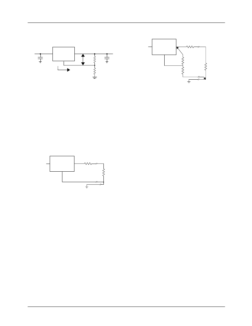
Figure 3. Basic Regulation Circuit
Load Regulation
It is not possible to provide true remote load sensing because
the FAN1084 series are three-terminal devices. Load regula-
tion is limited by the resistance of the wire connecting the reg-
ulator to the load. Load regulation per the data sheet
specification is measured at the bottom of the package.
For fixed voltage devices, negative side sensing is a true
Kelvin connection with the ground pin of the device returned
to the negative side of the load. This is illustrated in Figure 4.
Figure 4. Connection for Best Load Regulation
For adjustable voltage devices, negative side sensing is a true
Kelvin connection with the bottom of the output divider
returned to the negative side of the load. The best load regula-
tion is obtained when the top of the resistor divider R1 connects
directly to the regulator output and not to the load. Figure 5
illustrates this point.
If R1 connects to the load, then the effective resistance
between the regulator and the load would be:
R
P
X (1 + R2/R1), R
P
= Parasitic Line Resistance
The connection shown in Figure 5 does not multiply R
P
by the
divider ration. As an example, R
P
is about four milliohms per
foot with 16-gauge wire. This translates to 4mV per foot at 1A
load current. At higher load currents, this drop represents a
significant percentage of the overall regulation. It is important
to keep the positive lead between the regulator and the load as
short as possible and to use large wire or PC board traces.
Figure 5. Connection for Best load Regulation
Thermal Conditions
The FAN1084 series protect themselves under overload con-
ditions with internal power and thermal limiting circuitry.
However, for normal continuous load conditions, do not
exceed maximum junction temperature ratings. It is impor-
tant to consider all sources of thermal resistance from junc-
tion-to-ambient. These sources include the junction-to-case
resistance, the case-to-heatsink interface resistance, and the
heat sink resistance. Thermal resistance specifications have
been developed to more accurately reflect device tempera-
ture and ensure safe operating temperatures. The electrical
characteristics section provides a separate thermal resistance
and maximum junction temperature for both the control cir-
cuitry and the power transistor. Calculate the maximum junc-
tion temperature for both sections to ensure that both thermal
limits are met.
For example, look at using an FAN1084T to generate 4.5A
@ 1.5V from a 3.3V source (3.2V to 3.6V).
Assumptions
V
IN
= 3.6V worst case
V
OUT
= 1.475V worst case
I
OUT
= 4.5A continuous
T
A
= 60
°
C
θ
Case-to-Ambient
= 5
°
C/W (assuming both a heatsink and
a thermally conductive material)
The power dissipation in this application is:
P
D
= (V
IN
– V
OUT
) * (I
OUT
) = (3.6 – 1.475) * (4.5) = 9.6W
From the specification table:
T
J
= T
A
+ (P
D
) * (
θ
Case-to-Ambient
+
θ
JC
)
= 60 + (9.6) * (5 + 3) = 137
°
C
The junction temperature is below the maximum thermal
limit.
FAN1084
ADJ
C2
22
μ
F
V
OUT
+
C1
10
μ
F
I
ADJ
35
μ
A
+
IN
OUT
V
IN
V
OUT
= V
REF
(1 + R2/R1) + I
ADJ
(R2)
R1
R2
V
REF
FAN1084-1.5
IN
GND
R
L
R
P
Parasitic
Line Resistance
OUT
V
IN
FAN1084
ADJ
R
L
R1*
R2*
*Connect R1 to case
Connect R2 to load
R
P
Parasitic
Line Resistance
IN
OUT
V
IN
相关PDF资料 |
PDF描述 |
|---|---|
| FAN8026DTF | MOTOR CONTROLLER |
| FAN8034L | Controller Miscellaneous - Datasheet Reference |
| FAN8001DTF | Servo/Spindle Motor Controller/Driver |
| FAN8002D2 | Servo Motor Controller/Driver |
| FAN8005D2 | Servo Motor Controller/Driver |
相关代理商/技术参数 |
参数描述 |
|---|---|
| FAN8026DTF | 制造商:未知厂家 制造商全称:未知厂家 功能描述:MOTOR CONTROLLER |
| FAN8026G3 | 制造商:FAIRCHILD 制造商全称:Fairchild Semiconductor 功能描述:5-CH Motor Driver |
| FAN8026G3X | 功能描述:马达/运动/点火控制器和驱动器 5CH Motor drive IC RoHS:否 制造商:STMicroelectronics 产品:Stepper Motor Controllers / Drivers 类型:2 Phase Stepper Motor Driver 工作电源电压:8 V to 45 V 电源电流:0.5 mA 工作温度:- 25 C to + 125 C 安装风格:SMD/SMT 封装 / 箱体:HTSSOP-28 封装:Tube |
| FAN8033 | 功能描述:马达/运动/点火控制器和驱动器 Motor Driver IC 6 Channel RoHS:否 制造商:STMicroelectronics 产品:Stepper Motor Controllers / Drivers 类型:2 Phase Stepper Motor Driver 工作电源电压:8 V to 45 V 电源电流:0.5 mA 工作温度:- 25 C to + 125 C 安装风格:SMD/SMT 封装 / 箱体:HTSSOP-28 封装:Tube |
| FAN8034 | 制造商:FAIRCHILD 制造商全称:Fairchild Semiconductor 功能描述:6-CH Motor Driver |
发布紧急采购,3分钟左右您将得到回复。