- 您现在的位置:买卖IC网 > PDF目录67429 > FC250H1 (LINEAGE POWER LLC) DC-DC REG PWR SUPPLY MODULE PDF资料下载
参数资料
| 型号: | FC250H1 |
| 厂商: | LINEAGE POWER LLC |
| 元件分类: | 电源模块 |
| 英文描述: | DC-DC REG PWR SUPPLY MODULE |
| 封装: | MODULE-20 |
| 文件页数: | 4/20页 |
| 文件大小: | 564K |
| 代理商: | FC250H1 |
12
Lineage Power
Data Sheet
April 2008
18 Vdc to 36 Vdc Input, 24 Vdc Output; 250 W
FC250H1 Power Module: dc-dc Converter;
Feature Descriptions (continued)
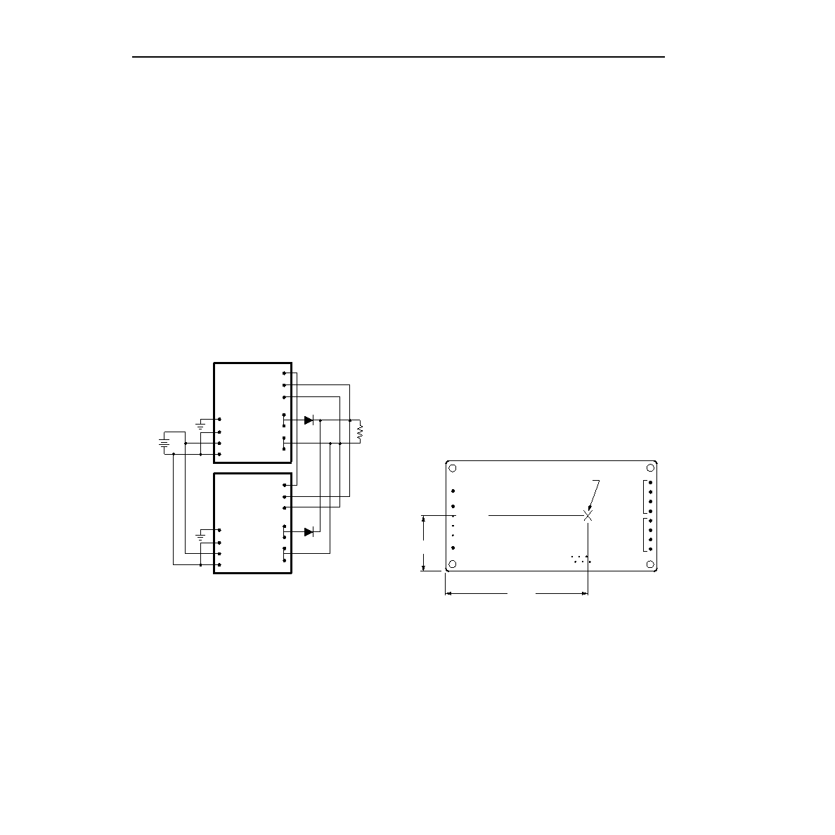
Forced Load Sharing (Parallel Operation)
(continued)
Good layout techniques should be observed for noise
immunity. To implement forced load sharing, the follow-
ing connections must be made:
s
The parallel pins of all units must be connected
together. The paths of these connections should be
as direct as possible.
s
All remote-sense pins should be connected to the
power bus at the same point, i.e., connect all
SENSE(+) pins to the (+) side of the power bus at the
same point and all SENSE(–) pins to the (–) side of
the power bus at the same point. Close proximity and
directness are necessary for good noise immunity.
When not using the parallel feature, leave the
PARALLEL pin open.
8-581 (C)
Figure 17. Wiring Conguration for Redundant
Parallel Operation
Power Good Signal
The PWR GOOD pin provides an open-drain signal
(referenced to the SENSE(–) pin) that indicates the
operating state of the module. A low impedance
(<100
) between PWR GOOD and SENSE(–) indi-
cates that the module is operating. A high impedance
(>1 M
) between PWR GOOD and SENSE(–) indi-
cates that the module is off or has failed. The PWR
GOOD pin can be pulled up through a resistor to an
external voltage to facilitate sensing. This external volt-
age level must not exceed 40 V, and the current into the
PWR GOOD pin during the low-impedance state
should be limited to 1 mA maximum.
Thermal Considerations
Introduction
The power modules operate in a variety of thermal
environments; however, sufcient cooling should be
provided to help ensure reliable operation of the unit.
Heat-dissipating components inside the unit are ther-
mally coupled to the case. Heat is removed by conduc-
tion, convection, and radiation to the surrounding
environment. Proper cooling can be veried by mea-
suring the case temperature. Peak temperature occurs
at the position indicated in Figure 18.
8-1303 (C).a
Note: Top view, measurements shown in millimeters and (inches).
Pin locations are for reference only.
Figure 18. Case Temperature Measurement
Location
VO(+)
PARALLEL
SENSE(+)
SENSE(–)
VO(–)
CASE
VI(+)
ON/OFF
VI(–)
VO(+)
PARALLEL
SENSE(+)
SENSE(–)
VO(–)
CASE
VI(+)
ON/OFF
VI(–)
30.5
(1.20)
82.6
(3.25)
CASE
SYNC IN
VI(–)
VI(+)
VO(+)
VO(–)
SYNC OUT
MEASURE CASE
TEMPERATURE HERE
ON/OFF
相关PDF资料 |
PDF描述 |
|---|---|
| FC250H1 | 1-OUTPUT 250 W DC-DC REG PWR SUPPLY MODULE |
| FC250H1 | 1-OUTPUT 250 W DC-DC REG PWR SUPPLY MODULE |
| FC30 | SPECIALTY ANALOG CIRCUIT, PBGA14 |
| FC30TR | SPECIALTY ANALOG CIRCUIT, PBGA14 |
| FCD4A14CCB | IMAGE SENSOR, UUC19 |
相关代理商/技术参数 |
参数描述 |
|---|---|
| FC250R | 制造商:MA-COM 制造商全称:M/A-COM Technology Solutions, Inc. 功能描述:Power Module:dc-dc Converter; 18 Vdc to 36 Vdc Input, 28 Vdc Output; 250 W |
| FC250R1 | 制造商:MA-COM 制造商全称:M/A-COM Technology Solutions, Inc. 功能描述:Power Module:dc-dc Converter; 18 Vdc to 36 Vdc Input, 28 Vdc Output; 250 W |
| FC2528 | 制造商: 功能描述: 制造商:undefined 功能描述: |
| FC252U | 制造商:AB 功能描述:POT2.5K ALLEN BRADLEY S7D7B |
| FC255 | 制造商:未知厂家 制造商全称:未知厂家 功能描述:THIN SMD LOW / MEDIUM FREQUENCY CRYSTAL UNIT |
发布紧急采购,3分钟左右您将得到回复。