- 您现在的位置:买卖IC网 > PDF目录67504 > FM32276-GTR SPECIALTY CONSUMER CIRCUIT, PDSO14 PDF资料下载
参数资料
| 型号: | FM32276-GTR |
| 元件分类: | 消费家电 |
| 英文描述: | SPECIALTY CONSUMER CIRCUIT, PDSO14 |
| 封装: | GREEN, MS-012AB, SOIC-14 |
| 文件页数: | 18/21页 |
| 文件大小: | 417K |
| 代理商: | FM32276-GTR |
FM32278/276/274/272 - 5V I2C Companion
Rev. 3.1
July 2010
Page 6 of 21
The voltage on the PFI input pin is compared to an
onboard 1.2V reference. When the PFI input voltage
drops below this threshold, the comparator will drive
the PFO pin to a low state. The comparator has 100
mV (max) of hysteresis to reduce noise sensitivity,
only for a rising PFI signal. For a falling PFI edge,
there is no hysteresis.
The comparator is a general purpose device and its
application is not limited to the NMI function.
Note: The maximum voltage on the comparator input PFI
is limited to 3.75V under normal operating conditions.
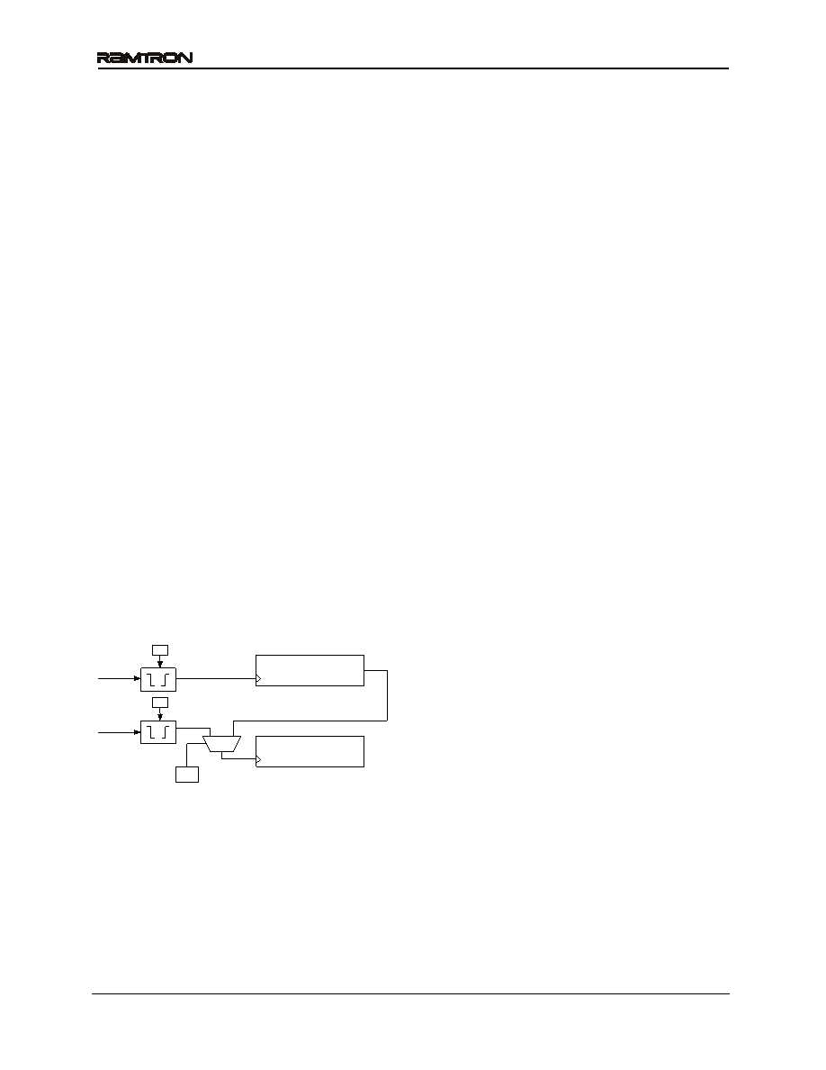
Event Counter
The FM3227x offers the user two battery-backed
event counters. Input pins CNT1 and CNT2 are
programmable edge detectors. Each clocks a 16-bit
counter. When an edge occurs, the counters will
increment their respective registers. Counter 1 is
located in registers 0Dh and 0Eh, Counter 2 is
located in registers 0Fh and 10h. These register
values can be read anytime VDD is above VTP, and
they will be incremented as long as a valid VBAK
power source is provided. To read, set the RC bit
register 0Ch bit 3 to 1. This takes a snapshot of all
four counter bytes allowing a stable value even if a
count occurs during the read. The registers can be
written by software allowing the counters to be
cleared or initialized by the system. Counts are
blocked during a write operation. The two counters
can be cascaded to create a single 32-bit counter by
setting the CC control bit (register 0Ch). When
cascaded, the CNT1 input will cause the counter to
increment. CNT2 is not used in this mode.
Figure 6. Event Counter
The control bits for event counting are located in
register 0Ch. Counter 1 Polarity is bit C1P, bit 0;
Counter 2 Polarity is C2P, bit 1; the Cascade Control
is CC, bit 2; and the Read Counter bit is RC bit 3.
The polarity bits must be set prior to setting the
counter value(s). If a polarity bit is changed, the
counter may inadvertently increment. If the counter
pins are not being used, tie them to ground.
Serial Number
A memory location to write a 64-bit serial number is
provided. It is a writeable nonvolatile memory block
that can be locked by the user once the serial number
is set. The 8 bytes of data and the lock bit are all
accessed via the device ID for the processor
companion. Therefore the serial number area is
separate and distinct from the memory array. The
serial number registers can be written an unlimited
number of times, so these locations are general
purpose memory. However once the lock bit is set the
values cannot be altered and the lock cannot be
removed. Once locked the serial number registers can
still be read by the system.
The serial number is located in registers 11h to 18h.
The lock bit is SNL, register 0Bh bit 7. Setting the
SNL bit to a 1 disables writes to the serial number
registers, and the SNL bit cannot be cleared.
Backup Power
The event counter and battery-backed registers may
be powered with a backup power source. When the
primary system power fails, the voltage on the VDD
pin will drop. When VDD is less than 2.5V, the event
counters and battery-backed registers will switch to
the backup power supply on VBAK.
A battery may be inserted into a system board
without any concern for excessive current draw on
the FM3227x’s VBAK pin.
Trickle Charger
To facilitate capacitor backup, the VBAK pin can
optionally provide a trickle charge current. When the
VBC bit, register 0Bh bit 2, is set to ‘1’, the VBAK pin
will source approximately 80 A until VBAK reaches
3.75V. In 5V systems, this charges the capacitor to
VDD without an external diode and resistor charger
and also prevents the user from exceeding the VBAK
maximum voltage specification. There is a Fast
Charge mode which is enabled by the FC bit (register
0Bh, bit 5). In this mode the trickle charger current is
set to approximately 1 mA, allowing a large backup
capacitor to charge more quickly.
In the case where no backup source is used, the VBAK
pin should be tied to VSS. VBAK should not be tied to
5V since the VBAK (max) specification will be
exceeded. Be sure to turn off the trickle charger
(VBC=0), otherwise charger current will be shunted
to ground from VDD.
Note: systems using lithium batteries should clear the
VBC bit to 0 to prevent battery charging. The VBAK
circuitry includes an internal 1 K
series resistor as a
safety element. The trickle charger is UL Recognized.
16-bit Counter
CNT1
CC
CNT2
C1P
C2P
16-bit Counter
相关PDF资料 |
PDF描述 |
|---|---|
| FM32276-G | SPECIALTY CONSUMER CIRCUIT, PDSO14 |
| FM32278-GTR | SPECIALTY CONSUMER CIRCUIT, PDSO14 |
| FM32278-G | SPECIALTY CONSUMER CIRCUIT, PDSO14 |
| FM32L272-GTR | SPECIALTY CONSUMER CIRCUIT, PDSO14 |
| FM32L272-G | SPECIALTY CONSUMER CIRCUIT, PDSO14 |
相关代理商/技术参数 |
参数描述 |
|---|---|
| FM32278 | 制造商:RAMTRON 制造商全称:RAMTRON 功能描述:5V Integrated Processor Companion with Memory |
| FM32278-G | 功能描述:F-RAM 256K w/Pwr Mon WDT Bat Sw PF Ser Num RoHS:否 存储容量:512 Kbit 组织:64 K x 8 接口:SPI 工作电源电压:2 V to 3.6 V 工作温度范围:- 40 C to + 85 C 安装风格:SMD/SMT 封装 / 箱体:SOIC-8 封装:Tube 制造商:Cypress Semiconductor |
| FM32278-GTR | 功能描述:F-RAM 256K w/Pwr Mon WDT Bat Sw PF Ser Num RoHS:否 存储容量:512 Kbit 组织:64 K x 8 接口:SPI 工作电源电压:2 V to 3.6 V 工作温度范围:- 40 C to + 85 C 安装风格:SMD/SMT 封装 / 箱体:SOIC-8 封装:Tube 制造商:Cypress Semiconductor |
| FM3264 | 制造商:未知厂家 制造商全称:未知厂家 功能描述:Integrated Processor Companion with Memory |
| FM3264-G | 功能描述:监控电路 64K w/Pwr Mon WDT Bat Sw Pwr Fail RoHS:否 制造商:STMicroelectronics 监测电压数: 监测电压: 欠电压阈值: 过电压阈值: 输出类型:Active Low, Open Drain 人工复位:Resettable 监视器:No Watchdog 电池备用开关:No Backup 上电复位延迟(典型值):10 s 电源电压-最大:5.5 V 最大工作温度:+ 85 C 安装风格:SMD/SMT 封装 / 箱体:UDFN-6 封装:Reel |
发布紧急采购,3分钟左右您将得到回复。