- 您现在的位置:买卖IC网 > PDF目录68995 > FN3000-810-830 PLL FREQUENCY SYNTHESIZER, DMA37 PDF资料下载
参数资料
| 型号: | FN3000-810-830 |
| 元件分类: | PLL合成/DDS/VCOs |
| 英文描述: | PLL FREQUENCY SYNTHESIZER, DMA37 |
| 文件页数: | 12/12页 |
| 文件大小: | 702K |
| 代理商: | FN3000-810-830 |
123456789012345678901234567890121234567890123456789012345678901212345678901234567890123456789012123456789012345678901234567890121234567890123456789012345678901212
201 McLean Blvd, Paterson, NJ 07504 Tel: (973) 881-8800 Fax: (973) 881-8361
E-mail: sales@synergymwave.com Web Site: http://www.synergymwave.com
[ 178 ]
This evaluation kit contains all the
hardware and software needed to
experiment with a line of extremely
low-noise frequency synthesizers.
Fractional-N frequency synthesizers
are difficult to design, and even more
challenging to evaluate. In the case
of Series-3000 fractional-N frequency
synthesizers from Synergy Microwave
Corp. (Paterson, NJ), the evaluation
effort has already been made
simpler. Engineers can use the
company’s versatile evaluation board
to “test drive” the fractional-N synthe-
sizers with different step sizes (as
small as 1 kHz), for output frequen-
cies from 50 to 3000 MHz in various
bandwidths. Ceramic resonator-
based units have a typical bandwidth
of 25 MHz, whereas microstrip or LC
based units have been designed for
optimized bandwidth and octave
bandwidths.
These fractional-N frequency synthe-
sizers (see Microwaves & RF, April,
1998, p. 151) provide switching
speeds on the order of 10 secs
and extremely low phase noise.
Fractional-N synthesizers incorporat-
ing a stable ceramic-resonator-
based voltage-controlled oscillator
(VCO), were tested with a variety of
step sizes from 1 kHz to several MHz.
The high quality factor (Q) of the
ceramic resonator helps to achieve
phase noise of -113 dBc/Hz offset 10
kHz from the carrier, -145 dBc/Hz
offset 800 kHz from the carrier, -150
dBc/Hz offset 3 MHz from the carrier.
At offset frequencies of 10 kHz
(typical) and higher, the phase noise
of the synthesizer is equal to that of
the basic VCO. The fractional-N
synthesizers cater to the need for
high-dynamic range applications
such as transceivers and test
equipment. Ceramic-resonator-
based fractional-N synthesizers with
about 25 MHz tuning range are the
optimum choice for narrowband base
station applications such as cellular,
Global System for Mobile Communi-
cations (GSM), and Personal Com-
munications Services (PCS).
Evaluation of such low-noise synthe-
sizers requires associated circuitry
that will not degrade the synthesizer’s
performance. The fractional-N
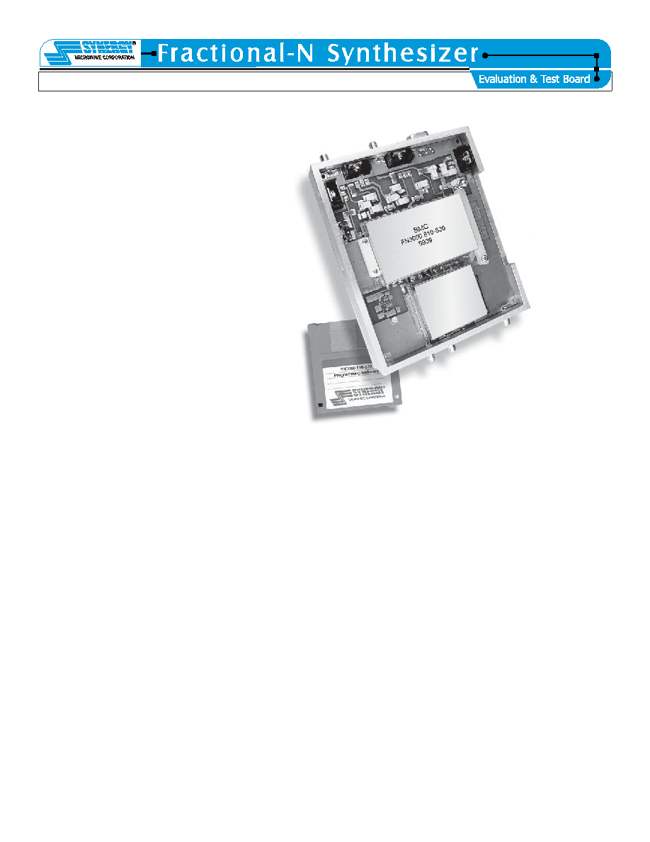
synthesizer evaluation board (see
figure) houses low-noise power-
supply (DC) conditioning and
regulating circuits as well as ultra-
low noise reference oscillator. Since
phase noise and spurious perfor-
mance depend on noise, hum, and
ripple of the power supply as well as
the spectral purity of the reference
oscillator, the basic frequency
synthesizer board already incorpo-
rates isolation circuitry for various
power supplies to minimize the
external influence.
The evaluation board is equipped
with 120-MHz or an optional 130-MHz
low-noise crystal frequency reference
oscillator. This source can be phase
locked to an external 10-MHz highly
stable reference. With the 130-MHz
reference, it can also be phase
locked to 13 MHz external reference
as typical for GSM applications. The
board can also be ordered without
the internal reference for use with an
external frequency reference source,
although this is only recommended
when a high-performance crystal
standard is available.
A fractional-N synthesizer can be
tested by clamping it to the evaluation
board; solder attachments are not
needed. Spring-loaded contacts
allow for evaluating various fractional-
N synthesizer models with the same
evaluation board. All ports, other than
programming ports, are equipped
with female SMA connectors. The
programming ports are hard-wired
using a flexible cable with mating
connector for direct connection to the
parallel printer port of a personal
computer.
The rugged and reliable evaluation
board is supplied with a floppy disk
containing programming software for
the fractional-N synthesizers. The
user-friendly dos-based software
runs on a standard personal comput-
er. It allows a user to vary numerous
synthesizer operating parameters,
including step size, reference
frequency, and output frequency
during evaluation. For those needing
to speed their designs to market, the
circuit design and layout of the
evaluation board can be readily
adapted and duplicated for final
system designs.
相关PDF资料 |
PDF描述 |
|---|---|
| FNA41060 | AC MOTOR CONTROLLER, DMA26 |
| FNB41560 | AC MOTOR CONTROLLER, DMA26 |
| FNW500R4 | 1-OUTPUT 504 W DC-DC REG PWR SUPPLY MODULE |
| FNW500R64-18 | 1-OUTPUT 504 W DC-DC REG PWR SUPPLY MODULE |
| FNW700R4 | 1-OUTPUT 700 W DC-DC REG PWR SUPPLY MODULE |
相关代理商/技术参数 |
参数描述 |
|---|---|
| FN-300-50 | 制造商:TE Connectivity 功能描述:SHUNT; Current Rating:300A; Sensing Element:Copper Alloy; Operating Temperature Min:-20C; Operating Temperature Max:60C; Accuracy: 0.25%; Mounting Type:Base; Operating Temperature Range:-20C to +60C; Output Voltage:50mV ;RoHS Compliant: NA |
| FN3025HL-10-71 | 功能描述:电源线滤波器 ADV EMC/RFI 10A FILTER 3-PHASE RoHS:否 制造商:EPCOS 电压额定值:277 VAC 电流额定值:100 A 安装风格:Chassis 端接类型:Screw |
| FN3025HL-20/71 | 制造商:Schaffner 功能描述:EMI FILTER |
| FN3025HL-20-71 | 功能描述:电源线滤波器 20A 11kW L Performance Level RoHS:否 制造商:EPCOS 电压额定值:277 VAC 电流额定值:100 A 安装风格:Chassis 端接类型:Screw |
| FN3025HL-30-71 | 功能描述:电源线滤波器 30A 18.5kW L Performance Level RoHS:否 制造商:EPCOS 电压额定值:277 VAC 电流额定值:100 A 安装风格:Chassis 端接类型:Screw |
发布紧急采购,3分钟左右您将得到回复。