- 您现在的位置:买卖IC网 > PDF目录1794 > FSDL321 (Fairchild Semiconductor)IC SWIT PWM GREEN CM OVP HV 8DIP PDF资料下载
参数资料
| 型号: | FSDL321 |
| 厂商: | Fairchild Semiconductor |
| 文件页数: | 10/20页 |
| 文件大小: | 0K |
| 描述: | IC SWIT PWM GREEN CM OVP HV 8DIP |
| 产品变化通告: | Passivation Layer Change 07/Dec/2007 |
| 标准包装: | 50 |
| 输出隔离: | 隔离 |
| 频率范围: | 45kHz ~ 55kHz |
| 输入电压: | 8 V ~ 20 V |
| 输出电压: | 650V |
| 功率(瓦特): | 17W |
| 工作温度: | 25°C ~ 140°C |
| 封装/外壳: | 8-DIP(0.300",7.62mm) |
| 供应商设备封装: | 8-DIP |
| 其它名称: | FSDL321_NL FSDL321_NL-ND |
�� �
�
�FSDH321,� FSDL321�
�Functional� Description�
�1.� Startup� :� In� previous� generations� of� Fairchild� Power�
�Switches� (FPS� TM� )� the� Vstr� pin� had� an� external� resistor� to� the�
�DC� input� voltage� line.� In� this� generation� the� startup� resistor�
�is� replaced� by� an� internal� high� voltage� current� source� and� a�
�switch� that� shuts� off� when� 15mS� goes� by� after� the� supply�
�voltage,� Vcc,� gets� above� 12V.� The� source� turns� back� on� if�
�Vcc� drops� below� 8V.�
�Vo�
�431�
�Vfb�
�FB�
�3�
�Cfb�
�Vcc�
�5uA�
�D1�
�Vref�
�0.9mA�
�D2�
�Vfb*�
�2.5R�
�R�
�OSC�
�Gate�
�driver�
�Vin,dc�
�V� SD�
�OLP�
�Istr�
�Vstr�
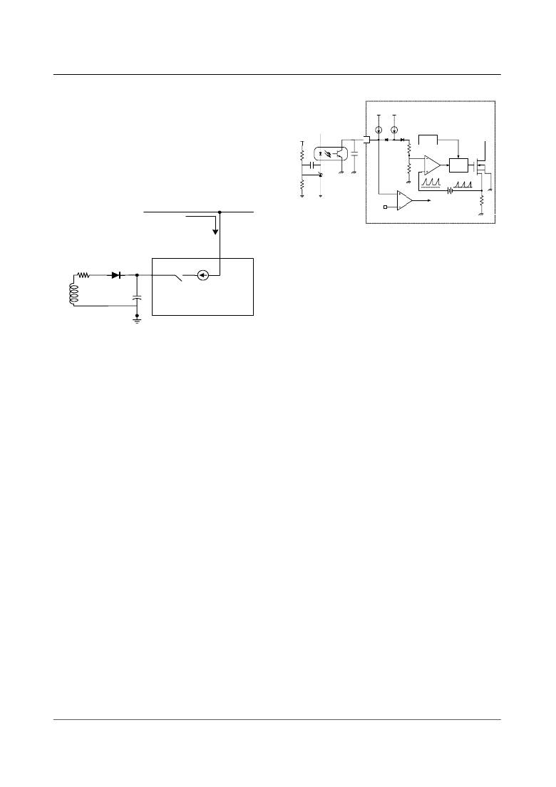
�Figure� 5.� Pulse� width� modulation� (PWM)� circuit�
�Vcc�
�UVLO� <8V�
�on�
�15m� S� After� UVLO�
�start(>12V)�
�off�
�J-FET�
�4.� Protection� Circuit� :� The� FPS� TM� has� several� protective�
�functions� such� as� over� load� protection� (OLP),� over� voltage�
�protection� (OVP),� abnormal� over� current� protection�
�(AOCP),� under� voltage� lock� out� (UVLO)� and� thermal� shut-�
�down� (TSD).� Because� these� protection� circuits� are� fully� inte-�
�grated� inside� the� IC� without� external� components,� the�
�reliability� is� improved� without� increasing� cost.� Once� the�
�fault� condition� occurs,� switching� is� terminated� and� the� Sense�
�Figure� 4.� High� voltage� current� source�
�2.� Feedback� Control� :� The� FSDx321� employs� current� mode�
�control,� shown� in� figure� 5.� An� opto-coupler� (such� as� the�
�H11A817A)� and� shunt� regulator� (such� as� the� KA431)� are�
�typically� used� to� implement� the� feedback� network.� Compar-�
�ing� the� feedback� voltage� with� the� voltage� across� the� Rsense�
�resistor� plus� an� offset� voltage� makes� it� possible� to� control� the�
�switching� duty� cycle.� When� the� reference� pin� voltage� of� the�
�KA431� exceeds� the� internal� reference� voltage� of� 2.5V,� the�
�H11A817A� LED� current� increases,� thus� pulling� down� the�
�feedback� voltage� and� reducing� the� duty� cycle.� This� event�
�typically� happens� when� the� input� voltage� is� increased� or� the�
�output� load� is� decreased.�
�3.� Leading� edge� blanking� (LEB)� :� At� the� instant� the� inter-�
�nal� Sense� FET� is� turned� on,� there� usually� exists� a� high� cur-�
�rent� spike� through� the� Sense� FET,� caused� by� the� primary� side�
�capacitance� and� secondary� side� rectifier� diode� reverse� recov-�
�ery.� Excessive� voltage� across� the� Rsense� resistor� would� lead�
�to� incorrect� feedback� operation� in� the� current� mode� PWM�
�control.� To� counter� this� effect,� the� FPS� TM� employs� a� leading�
�edge� blanking� (LEB)� circuit.� This� circuit� inhibits� the� PWM�
�comparator� for� a� short� time� (T� LEB� )� after� the� Sense� FET� is�
�turned� on.�
�FET� remains� off.� This� causes� Vcc� to� fall.� When� Vcc� reaches�
�the� UVLO� stop� voltage,� 8V,� the� protection� is� reset� and� the�
�internal� high� voltage� current� source� charges� the� Vcc� capaci-�
�tor� via� the� Vstr� pin.� When� Vcc� reaches� the� UVLO� start� volt-�
�age,12V,� the� FPS� TM� resumes� its� normal� operation.� In� this�
�manner,� the� auto-restart� can� alternately� enable� and� disable�
�the� switching� of� the� power� Sense� FET� until� the� fault� condi-�
�tion� is� eliminated.�
�4.1� Over� Load� Protection� (OLP)� :� Overload� is� defined� as�
�the� load� current� exceeding� a� pre-set� level� due� to� an� unex-�
�pected� event.� In� this� situation,� the� protection� circuit� should�
�be� activated� in� order� to� protect� the� SMPS.� However,� even�
�when� the� SMPS� is� in� the� normal� operation,� the� over� load�
�protection� circuit� can� be� activated� during� the� load� transition.�
�In� order� to� avoid� this� undesired� operation,� the� over� load� pro-�
�tection� circuit� is� designed� to� be� activated� after� a� specified�
�time� to� determine� whether� it� is� a� transient� situation� or� an�
�overload� situation.� In� conjunction� with� the� Ipk� current� limit�
�pin� (if� used)� the� current� mode� feedback� path� would� limit� the�
�current� in� the� Sense� FET� when� the� maximum� PWM� duty�
�cycle� is� attained.� If� the� output� consumes� more� than� this� max-�
�imum� power,� the� output� voltage� (Vo)� decreases� below� the� set�
�voltage.� This� reduces� the� current� through� the� opto-coupler�
�LED,� which� also� reduces� the� opto-coupler� transistor� current,�
�thus� increasing� the� feedback� voltage� (Vfb).� If� Vfb� exceeds�
�3V,� the� feedback� input� diode� is� blocked� and� the� 5uA� Idelay�
�current� source� starts� to� charge� Cfb� slowly� up� to� Vcc.� In� this�
�condition,� Vfb� continues� increasing� until� it� reaches� 6V,� when�
�the� switching� operation� is� terminated� as� shown� in� figure� 6.�
�The� delay� time� for� shutdown� is� the� time� required� to� charge�
�10�
�相关PDF资料 |
PDF描述 |
|---|---|
| FSDM0565RBIWDTU | IC SWIT PWM GREEN CM HV I2PAK |
| FSDM0565RELDTU | IC PWM/SENSEFET 650V TO-220F-6 |
| FSDM07652RBWDTU | IC SWIT PWM GREEN CM HV TO220F |
| FSDM1265RBWDTU | IC SWIT PWM GREEN CM HV TO220F |
| FSDM311A | IC FPS PWM/SENSFET 650V 8DIP |
相关代理商/技术参数 |
参数描述 |
|---|---|
| FSDL321L | 功能描述:电源开关 IC - 配电 FPS for DVDP/STB RoHS:否 制造商:Exar 输出端数量:1 开启电阻(最大值):85 mOhms 开启时间(最大值):400 us 关闭时间(最大值):20 us 工作电源电压:3.2 V to 6.5 V 电源电流(最大值): 最大工作温度:+ 85 C 安装风格:SMD/SMT 封装 / 箱体:SOT-23-5 |
| FSDL321L_Q | 功能描述:电源开关 IC - 配电 FPS for DVDP/STB RoHS:否 制造商:Exar 输出端数量:1 开启电阻(最大值):85 mOhms 开启时间(最大值):400 us 关闭时间(最大值):20 us 工作电源电压:3.2 V to 6.5 V 电源电流(最大值): 最大工作温度:+ 85 C 安装风格:SMD/SMT 封装 / 箱体:SOT-23-5 |
| FSDLC01G-S | 制造商:AXIOMTEK 制造商全称:AXIOMTEK 功能描述:Capacity: 128MB to 32GB |
| FSDLC128-S | 制造商:AXIOMTEK 制造商全称:AXIOMTEK 功能描述:Capacity: 128MB to 32GB |
| FSDLC16G-S | 制造商:AXIOMTEK 制造商全称:AXIOMTEK 功能描述:Capacity: 128MB to 32GB |
发布紧急采购,3分钟左右您将得到回复。