- 您现在的位置:买卖IC网 > PDF目录11376 > GRM2165C1HR20BD01D (Murata Electronics North America)CAP CER 0.2PF 50V NP0 0805 PDF资料下载
参数资料
| 型号: | GRM2165C1HR20BD01D |
| 厂商: | Murata Electronics North America |
| 文件页数: | 167/182页 |
| 文件大小: | 0K |
| 描述: | CAP CER 0.2PF 50V NP0 0805 |
| 标准包装: | 4,000 |
| 系列: | GRM |
| 电容: | 0.20pF |
| 电压 - 额定: | 50V |
| 容差: | ±0.1pF |
| 温度系数: | C0G,NP0 |
| 安装类型: | 表面贴装,MLCC |
| 工作温度: | -55°C ~ 125°C |
| 应用: | 通用 |
| 封装/外壳: | 0805(2012 公制) |
| 尺寸/尺寸: | 0.079" L x 0.049" W(2.00mm x 1.25mm) |
| 厚度(最大): | 0.028"(0.70mm) |
| 包装: | 带卷 (TR) |
第1页第2页第3页第4页第5页第6页第7页第8页第9页第10页第11页第12页第13页第14页第15页第16页第17页第18页第19页第20页第21页第22页第23页第24页第25页第26页第27页第28页第29页第30页第31页第32页第33页第34页第35页第36页第37页第38页第39页第40页第41页第42页第43页第44页第45页第46页第47页第48页第49页第50页第51页第52页第53页第54页第55页第56页第57页第58页第59页第60页第61页第62页第63页第64页第65页第66页第67页第68页第69页第70页第71页第72页第73页第74页第75页第76页第77页第78页第79页第80页第81页第82页第83页第84页第85页第86页第87页第88页第89页第90页第91页第92页第93页第94页第95页第96页第97页第98页第99页第100页第101页第102页第103页第104页第105页第106页第107页第108页第109页第110页第111页第112页第113页第114页第115页第116页第117页第118页第119页第120页第121页第122页第123页第124页第125页第126页第127页第128页第129页第130页第131页第132页第133页第134页第135页第136页第137页第138页第139页第140页第141页第142页第143页第144页第145页第146页第147页第148页第149页第150页第151页第152页第153页第154页第155页第156页第157页第158页第159页第160页第161页第162页第163页第164页第165页第166页当前第167页第168页第169页第170页第171页第172页第173页第174页第175页第176页第177页第178页第179页第180页第181页第182页
�� �
�
�!� Note� ?� Please� read� rating� and� !� CAUTION� (for� storage,� operating,� rating,� soldering,� mounting� and� handling)� in� this� catalog� to� prevent� smoking� and/or� burning,� etc.�
�?� This� catalog� has� only� typical� speci?cations.� Therefore,� please� approve� our� product� speci?cations� or� transact� the� approval� sheet� for� product� speci?cations� before� ordering.�
�!� Caution�
�Continued� from� the� preceding� page.�
�3-2.� A� soldering� iron� with� a� tip� of� ?3mm� or� smaller� should�
�be� used.� It� is� also� necessary� to� keep� the� soldering�
�iron� from� touching� the� components� during� the� re-work.�
�3-3.� Solder� wire� with� ?0.5mm� or� smaller� is� required� for�
�soldering.�
�C02E.pdf�
�Sep.25,2013�
�<Applicable� to� KR3/KRM� Series>�
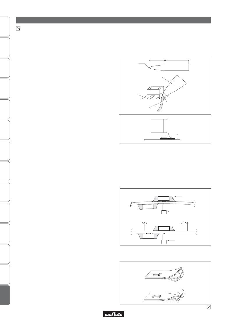
�4.� For� the� shape� of� the� soldering� iron� tip,� refer� to� the� figure�
�on� the� right.�
�Regarding� the� type� of� solder,� use� a� wire� diameter� of�
�?0.5mm� or� less� (rosin� core� wire� solder).�
�How� to� Apply� the� Soldering� Iron�
�17�
�R0.5�
�Tip� of� Soldering� Iron�
�Tip� temperature:� 350°C� or� less/�
�5� sec.� or� less/60W� or� less�
�26�
�(in� mm)�
�Apply� the� tip� of� the� soldering� iron� against� the� lower� end� of�
�the� metal� terminal.�
�1)� In� order� to� prevent� cracking� caused� by� sudden� heating� of�
�Copper� Land�
�Apply� the� tip� of� the� soldering� iron� only�
�the� ceramic� device,� do� not� touch� the� ceramic� base� directly.�
�2)� In� order� to� prevent� deviations� and� dislocating� of� the� chip,�
�do� not� touch� the� junction� of� the� chip� and� the� metal�
�terminal,� and� the� metal� portion� on� the� outside� directly.�
�Appropriate� Amount� of� Solder�
�The� amount� of� solder� for� corrections� by� soldering� iron,�
�should� be� lower� than� the� height� of� the� lower� side� of� the� chip.�
�5.� Washing�
�Excessive� ultrasonic� oscillation� during� cleaning� can� cause�
�the� PCBs� to� resonate,� resulting� in� cracked� chips� or� broken�
�solder� joints.� Take� note� not� to� vibrate� PCBs.�
�6.� Electrical� Test� on� Printed� Circuit� Board�
�1.� Confirm� position� of� the� backup� pin� or� specific� jig,� when�
�inspecting� the� electrical� performance� of� a� capacitor� after�
�mounting� on� the� printed� circuit� board.�
�1-1.� Avoid� bending� the� printed� circuit� board� by� the�
�Wire� Solder�
�[Not� Recommended]�
�on� the� terminal� portion,� without� touching�
�the� body� of� the� chip.�
�Cross� Section�
�Peeling�
�pressure� of� a� test-probe,� etc.�
�The� thrusting� force� of� the� test� probe� can� flex� the� PCB,�
�resulting� in� cracked� chips� or� open� solder� joints.�
�Provide� backup� pins� on� the� back� side� of� the� PCB� to�
�prevent� warping� or� flexing.� Install� backup� pins� as�
�close� to� the� capacitor� as� possible.�
�1-2.� Avoid� vibration� of� the� board� by� shock� when� a�
�test-probe� contacts� a� printed� circuit� board.�
�7.� Printed� Circuit� Board� Cropping�
�1.� After� mounting� a� capacitor� on� a� printed� circuit� board,� do�
�not� apply� any� stress� to� the� capacitor� that� causes� bending�
�or� twisting� the� board.�
�1-1.� In� cropping� the� board,� the� stress� as� shown� at� right�
�may� cause� the� capacitor� to� crack.�
�Cracked� capacitors� may� cause� deterioration� of� the�
�[Recommended]�
�[Bending]�
�[Twisting]�
�Backup� Pin�
�Test-probe�
�Test-probe�
�insulation� resistance,� and� result� in� a� short.�
�Avoid� this� type� of� stress� to� a� capacitor.�
�Continued� on� the� following� page.�
�148�
�相关PDF资料 |
PDF描述 |
|---|---|
| MAX355EWE+ | IC MULTIPLEXER DUAL 4X1 16SOIC |
| VE-J1J-IX-F2 | CONVERTER MOD DC/DC 36V 75W |
| MAX358EWE+ | IC MULTIPLEXER 8X1 16SOIC |
| MAX359EWE+ | IC MULTIPLEXER DUAL 4X1 16SOIC |
| GRM2165C1HR10BD01D | CAP CER 0.1PF 50V NP0 0805 |
相关代理商/技术参数 |
参数描述 |
|---|---|
| GRM2165C1HR30CD01D | 功能描述:多层陶瓷电容器MLCC - SMD/SMT 0805 0.30pF 50volt C0G +/-0.25pF RoHS:否 制造商:American Technical Ceramics (ATC) 电容:10 pF 容差:1 % 电压额定值:250 V 温度系数/代码:C0G (NP0) 外壳代码 - in:0505 外壳代码 - mm:1414 工作温度范围:- 55 C to + 125 C 产品:Low ESR MLCCs 封装:Reel |
| GRM2165C1HR40CD01D | 功能描述:多层陶瓷电容器MLCC - SMD/SMT 0805 0.40pF 50volt C0G +/-0.25pF RoHS:否 制造商:American Technical Ceramics (ATC) 电容:10 pF 容差:1 % 电压额定值:250 V 温度系数/代码:C0G (NP0) 外壳代码 - in:0505 外壳代码 - mm:1414 工作温度范围:- 55 C to + 125 C 产品:Low ESR MLCCs 封装:Reel |
| GRM2165C1HR47BD01D | 制造商:Murata Manufacturing Co Ltd 功能描述: |
| GRM2165C1HR47CD01D | 功能描述:多层陶瓷电容器MLCC - SMD/SMT 0805 0.47pF 50volt C0G +/-0.25pF RoHS:否 制造商:American Technical Ceramics (ATC) 电容:10 pF 容差:1 % 电压额定值:250 V 温度系数/代码:C0G (NP0) 外壳代码 - in:0505 外壳代码 - mm:1414 工作温度范围:- 55 C to + 125 C 产品:Low ESR MLCCs 封装:Reel |
| GRM2165C1HR50BD01B | 功能描述:多层陶瓷电容器MLCC - SMD/SMT 0805 0.50pF 50volt C0G +/-0.10pF RoHS:否 制造商:American Technical Ceramics (ATC) 电容:10 pF 容差:1 % 电压额定值:250 V 温度系数/代码:C0G (NP0) 外壳代码 - in:0505 外壳代码 - mm:1414 工作温度范围:- 55 C to + 125 C 产品:Low ESR MLCCs 封装:Reel |
发布紧急采购,3分钟左右您将得到回复。