- 您现在的位置:买卖IC网 > PDF目录223866 > GS880F32BGT-7IT (GSI TECHNOLOGY) 256K X 32 CACHE SRAM, 7 ns, PQFP100 PDF资料下载
参数资料
| 型号: | GS880F32BGT-7IT |
| 厂商: | GSI TECHNOLOGY |
| 元件分类: | SRAM |
| 英文描述: | 256K X 32 CACHE SRAM, 7 ns, PQFP100 |
| 封装: | TQFP-100 |
| 文件页数: | 13/22页 |
| 文件大小: | 621K |
| 代理商: | GS880F32BGT-7IT |
Rev: 1.00b 12/2002
20/22
2001, Giga Semiconductor, Inc.
Specifications cited are subject to change without notice. For latest documentation see http://www.gsitechnology.com.
GS880F18/32/36BT-5.5/6/6.5/7/7.5/8.5
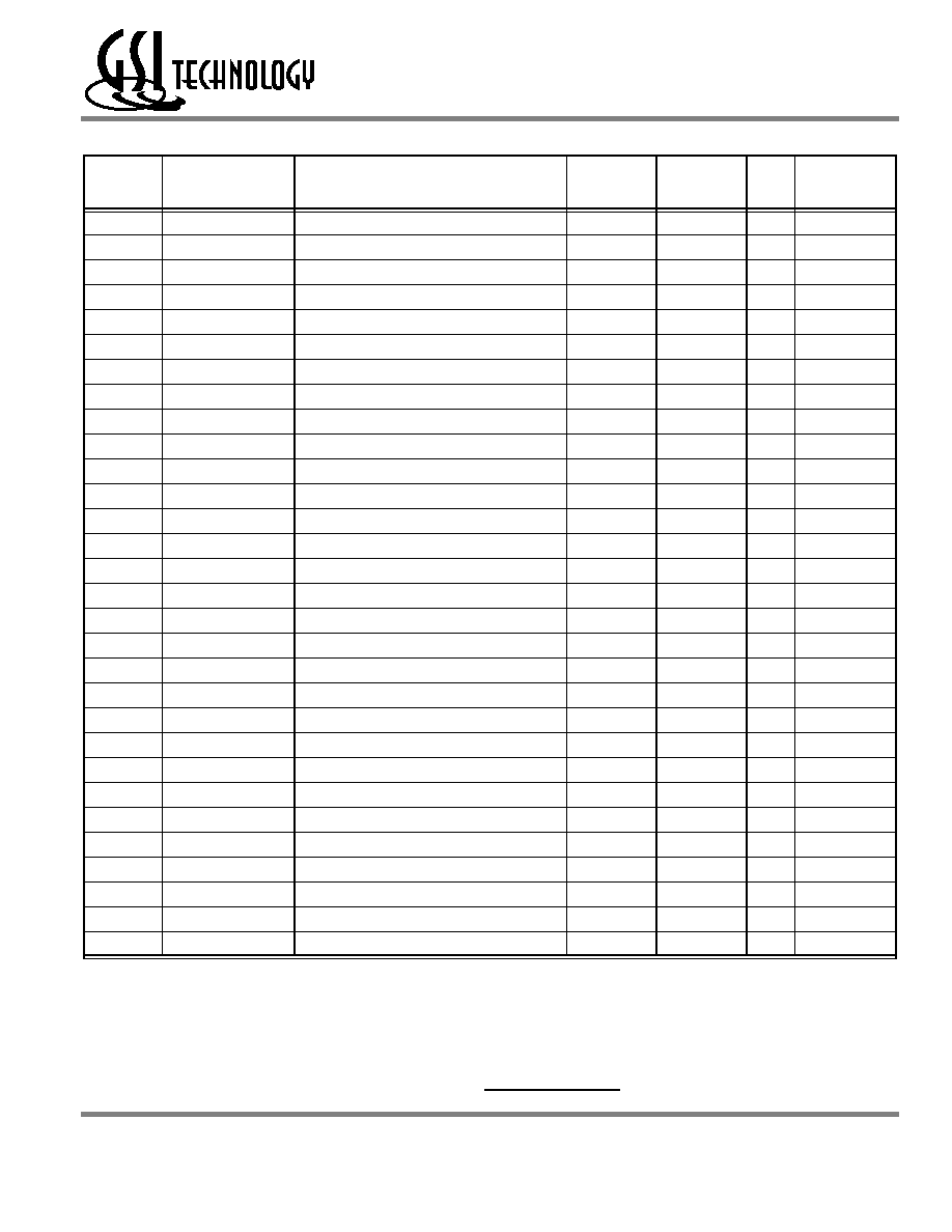
Ordering Information for GSI Synchronous Burst RAMs
Org
Part Number1
Type
Package
Speed2
(MHz/ns)
TA3
Status
512K x 18
GS880F18BT-5.5
Flow Through
TQFP
5.5
C
512K x 18
GS880F18BT-6
Flow Through
TQFP
6.0
C
512K x 18
GS880F18BT-6.5
Flow Through
TQFP
6.5
C
512K x 18
GS880F18BT-7
Flow Through
TQFP
7.0
C
512K x 18
GS880F18BT-7.5
Flow Through
TQFP
7.5
C
512K x 18
GS880F18BT-8.5
Flow Through
TQFP
8.5
C
256K x 32
GS880F32BT-5.5
Flow Through
TQFP
5.5
C
256K x 32
GS880F32BT-6
Flow Through
TQFP
6.0
C
256K x 32
GS880F32BT-6.5
Flow Through
TQFP
6.5
C
256K x 32
GS880F32BT-7
Flow Through
TQFP
7.0
C
256K x 32
GS880F32BT-7.5
Flow Through
TQFP
7.5
C
256K x 32
GS880F32BT-8.5
Flow Through
TQFP
8.5
C
256K x 36
GS880F36BT-5.5
Flow Through
TQFP
5.5
C
256K x 36
GS880F36BT-6
Flow Through
TQFP
6.0
C
256K x 36
GS880F36BT-6.5
Flow Through
TQFP
6.5
C
256K x 36
GS880F36BT-7
Flow Through
TQFP
7.0
C
256K x 36
GS880F36BT-7.5
Flow Through
TQFP
7.5
C
256K x 36
GS880F36BT-8.5
Flow Through
TQFP
8.5
C
512K x 18
GS880F18BT-5.5I
Flow Through
TQFP
5.5
I
512K x 18
GS880F18BT-6I
Flow Through
TQFP
6.0
I
512K x 18
GS880F18BT-6.5I
Flow Through
TQFP
6.5
I
512K x 18
GS880F18BT-7I
Flow Through
TQFP
7.0
I
512K x 18
GS880F18BT-7.5I
Flow Through
TQFP
7.5
I
512K x 18
GS880F18BT-8I
Flow Through
TQFP
8.5
I
256K x 32
GS880F32BT-5.5I
Flow Through
TQFP
5.5
I
256K x 32
GS880F32BT-6I
Flow Through
TQFP
6.0
I
256K x 32
GS880F32BT-6.5I
Flow Through
TQFP
6.5
I
256K x 32
GS880F32BT-7I
Flow Through
TQFP
7.0
I
256K x 32
GS880F32BT-7.5I
Flow Through
TQFP
7.5
I
256K x 32
GS880F32BT-8.5I
Flow Through
TQFP
8.5
I
Notes:
1. Customers requiring delivery in Tape and Reel should add the character “T” to the end of the part number. Example: GS880F18-6T.
2. The speed column indicates the cycle frequency (MHz) of the device in Pipeline mode and the latency (ns) in Flow Through mode. Each
device is Pipeline/Flow through mode-selectable by the user.
3. TA = C = Commercial Temperature Range. TA = I = Industrial Temperature Range.
4.
GSI offers other versions this type of device in many different configurations and with a variety of different features, only some of which
are covered in this data sheet. See the GSI Technology web site (www.gsitechnology.com) for a complete listing of current offerings.
相关PDF资料 |
PDF描述 |
|---|---|
| GSAA07C-Q01 | SNAP ACTING/LIMIT SWITCH, SPDT, MOMENTARY, 0.1A, 50VDC, PANEL MOUNT |
| GSAC36C-6Q02 | SNAP ACTING/LIMIT SWITCH, SPDT, MOMENTARY, 0.1A, 50VDC, PANEL MOUNT |
| GSAD28C-Q04 | SNAP ACTING/LIMIT SWITCH, DPDT, MOMENTARY, 0.1A, 50VDC, PANEL MOUNT |
| GSAD33C-6Q04 | SNAP ACTING/LIMIT SWITCH, SPDT, MOMENTARY, 0.1A, 50VDC, PANEL MOUNT |
| GSAD34C-Q02 | SNAP ACTING/LIMIT SWITCH, SPDT, MOMENTARY, 0.1A, 50VDC, PANEL MOUNT |
相关代理商/技术参数 |
参数描述 |
|---|---|
| GS880F32BT-4.5 | 制造商:GSI 制造商全称:GSI Technology 功能描述:512K x 18, 256K x 32, 256K x 36 9Mb Sync Burst SRAMs |
| GS880F32BT-4.5I | 制造商:GSI 制造商全称:GSI Technology 功能描述:512K x 18, 256K x 32, 256K x 36 9Mb Sync Burst SRAMs |
| GS880F32BT-5 | 制造商:GSI 制造商全称:GSI Technology 功能描述:512K x 18, 256K x 32, 256K x 36 9Mb Sync Burst SRAMs |
| GS880F32BT-5.5 | 制造商:GSI 制造商全称:GSI Technology 功能描述:512K x 18, 256K x 32, 256K x 36 9Mb Sync Burst SRAMs |
| GS880F32BT-5.5I | 制造商:GSI 制造商全称:GSI Technology 功能描述:512K x 18, 256K x 32, 256K x 36 9Mb Sync Burst SRAMs |
发布紧急采购,3分钟左右您将得到回复。