参数资料
| 型号: | HC55143IM |
| 厂商: | Intersil |
| 文件页数: | 6/36页 |
| 文件大小: | 0K |
| 描述: | IC SLIC UNIVERSAL LP 32-PLCC |
| 标准包装: | 30 |
| 系列: | UniSLIC14 |
| 功能: | 用户线路接口概念(SLIC) |
| 电路数: | 1 |
| 电源电压: | 4.75 V ~ 5.25 V |
| 电流 - 电源: | 2.25mA |
| 功率(瓦特): | 1.4W |
| 工作温度: | -40°C ~ 85°C |
| 安装类型: | 表面贴装 |
| 封装/外壳: | 32-LCC(J 形引线) |
| 供应商设备封装: | 32-PLCC |
| 包装: | 管件 |
| 包括: | 电池跟踪抗削顶失真,回路和接地键检测,振铃控制 |
第1页第2页第3页第4页第5页当前第6页第7页第8页第9页第10页第11页第12页第13页第14页第15页第16页第17页第18页第19页第20页第21页第22页第23页第24页第25页第26页第27页第28页第29页第30页第31页第32页第33页第34页第35页第36页
14
FN4659.13
June 1, 2006
23. Four-Wire to Two-Wire Gain Tracking - The 4-wire to 2-wire
gain tracking is referenced to measurements taken for
ERX = -10dBm, 1.0kHz signal, EG source removed from circuit,
RL = 600 and is computed using the following equation:
G4-2 = 20 log (VTR/ERX) vary amplitude -40dBm to +3dBm, or
-55dBm to -40dBm and compare to -10dBm reading.
VTR, RL and ERX are defined in Figure 8. The level is specified at
the 4-wire receive port and referenced to a 600
impedance level.
24. Two-Wire Idle Channel Noise - The 2-wire idle channel noise
at VTR is specified with the 2-wire port terminated in 600 (RL)
and with the 4-wire receive port (VTX) floating (Reference
Figure 9).
25. Four-Wire Idle Channel Noise - The 4-wire idle channel noise
at VTX is specified with the 2-wire port terminated in 600 (RL).
The noise specification is with respect to a 600
impedance
level at VTX. The 4-wire receive port (VTX) floating (Reference
Figure 9).
26. Harmonic Distortion (2-Wire to 4-Wire) - The harmonic
distortion is measured within the voice band with the following
conditions. EG = 0dBm at 1kHz, RL = 600. Measurement
taken at VTX. (Reference Figure 7).
27. Harmonic Distortion (4-Wire to 2-Wire) - The harmonic
distortion is measured within the voice band with the following
conditions. ERX = 0dBm0. Vary frequency between 300Hz and
3.4kHz, RL = 600. Measurement taken at VTR. (Reference
Figure 8).
28. Constant Loop Current - The constant loop current is
calculated using the following equation:
IL = 1000/RLIM = VTR/600 (Reference Figure 10).
29. Ground Key Detector - (TRIGGER) Ground the Ring pin
through a 2.5k
resistor and verify that GKD goes low.
(RESET) Disconnect the Ring pin and verify that GKD goes
high.
(Hysteresis) Compare difference between trigger and reset.
30. Electrical Test - Not tested in production at -40°C.
Circuit Operation and Design Information
The UniSLIC14 family of SLICs are voltage feed current
sense Subscriber Line Interface Circuits (SLIC). For short
loop applications, the voltage between the tip and ring
terminals varies to maintain a constant loop current. For long
loop applications, the voltage between the tip and ring
terminals are relatively constant and the loop current varies
in proportion to the load.
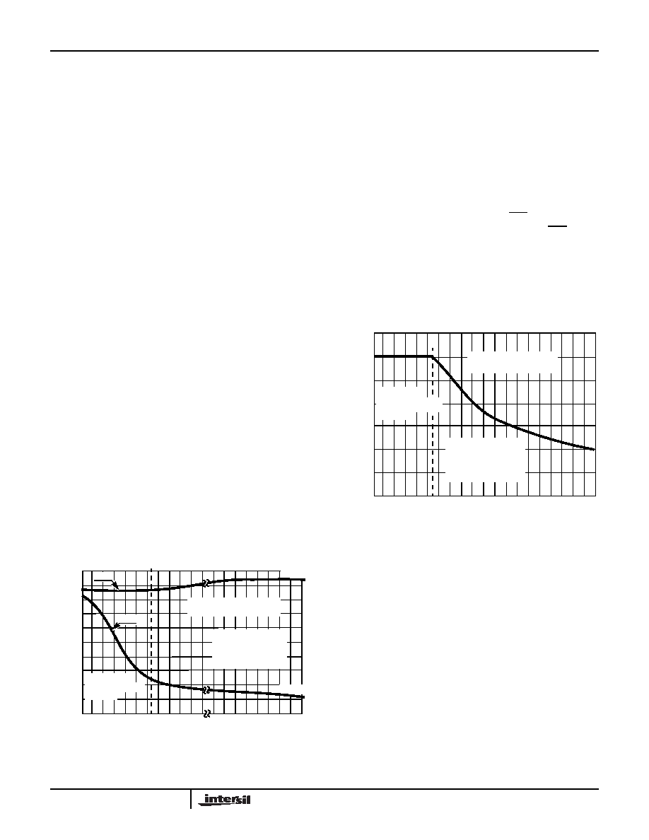
The tip and ring voltages for various loop resistances are
shown in Figure 13. The tip voltage remains relatively
constant as the ring voltage moves to limit the loop current
for short loops.
The loop current for various loop resistances are shown in
Figure 14. For short loops, the loop current is limited to the
programmed current limit, set by RILIM. For long loop
applications, the loop current varies in accordance with
Ohms law for the given tip to ring voltage and the loop
resistance.
.
The following discussion separates the SLIC’s operation into
its DC and AC paths, then follows up with additional circuit
and design information.
DC Feed Curve
The DC feed curve for the UniSLIC14 family is user
programmable. The user defines the on hook and off hook
overhead voltages (including the overhead voltage for off
hook pulse metering if applicable), the maximum and
minimum loop current limits, the switch hook detect
threshold and the battery voltage. From these requirements,
the DC feed curve is customized for optimum operation in
any given application. An Excel spread sheet to calculate the
external components can be downloaded off our web site
www.intersil.com/telecom/unislic14.xls.
FIGURE 13. TIP AND RING VOLTAGES vs LOOP RESISTANCE
TIP
AND
RING
VOLTA
GES
(V
)
LOOP RESISTANCE (
)
0
-5
-10
-15
-20
-25
-30
-35
-50
-40
-45
200
600 1000 1400 1800 2000
4K
10K
6K
8K
CONSTANT
LOOP CURRENT
REGION
VBH = -48V
RD = 41.2k
ROH = 38.3k
RDC_RAC = 19.6k
RILim = 33.2k
CONSTANT TIP TO RING
VOLTAGE REGION
-44.5V
-2.5V
TIP
RING
FIGURE 14. LOOP CURRENT vs LOOP RESISTANCE
LOOP
CURR
E
N
T
(mA)
0
LOOP RESISTANCE (
)
200
600
1K
1.4K 1.8K 2.2K 2.6K
3.8K
3.0K 3.4K
35
30
25
20
15
10
5
CONSTANT
LOOP CURRENT
REGION
VBH = -48V
RD = 41.2k
ROH = 38.3k
RDC_RAC = 19.6k
RILim = 33.2k
CONSTANT TIP TO RING
VOLTAGE REGION
HC55120, HC55121, HC55130, HC55140, HC55142, HC55143, HC55150
相关PDF资料 |
PDF描述 |
|---|---|
| HC5515CMZ | IC SLIC ITU CO/PABX LP 28-PLCC |
| HC9P5504B-5ZX96 | IC SLIC EIA/ITU PABX 24-SOIC |
| HD3-6402R-9Z | IC UART CMOS 5V 2MHZ 40-DIP |
| HD9P6409-9Z96 | IC MED MANCHESTER 1MHZ 20-SOIC |
| HI1-0390-2 | IC SWITCH DUAL SPDT 16CDIP |
相关代理商/技术参数 |
参数描述 |
|---|---|
| HC5514X | 制造商:Harris Corporation 功能描述: |
| HC5514XB | 制造商:Harris Corporation 功能描述: |
| HC5514XEVAL1 | 功能描述:界面开发工具 UNISLIC14 FAMILY EVALUATION BRD RoHS:否 制造商:Bourns 产品:Evaluation Boards 类型:RS-485 工具用于评估:ADM3485E 接口类型:RS-485 工作电源电压:3.3 V |
| HC5514XEVAL2 | 功能描述:界面开发工具 EVALRD TO GO W/IDT MOTHER BRD RoHS:否 制造商:Bourns 产品:Evaluation Boards 类型:RS-485 工具用于评估:ADM3485E 接口类型:RS-485 工作电源电压:3.3 V |
| HC5514XEVAL3 | 功能描述:EVAL BOARD TI CODEC MOTHER BOARD RoHS:否 类别:编程器,开发系统 >> 过时/停产零件编号 系列:UniSLIC14 标准包装:1 系列:- 传感器类型:CMOS 成像,彩色(RGB) 传感范围:WVGA 接口:I²C 灵敏度:60 fps 电源电压:5.7 V ~ 6.3 V 嵌入式:否 已供物品:成像器板 已用 IC / 零件:KAC-00401 相关产品:4H2099-ND - SENSOR IMAGE WVGA COLOR 48-PQFP4H2094-ND - SENSOR IMAGE WVGA MONO 48-PQFP |
发布紧急采购,3分钟左右您将得到回复。