- 您现在的位置:买卖IC网 > PDF目录22310 > HIP6019BCB-T (Intersil)IC REG QD BCK/LINEAR 28-SOIC PDF资料下载
参数资料
| 型号: | HIP6019BCB-T |
| 厂商: | Intersil |
| 文件页数: | 12/15页 |
| 文件大小: | 0K |
| 描述: | IC REG QD BCK/LINEAR 28-SOIC |
| 标准包装: | 1,000 |
| 拓扑: | 降压(降压)同步(2),线性(LDO)(2) |
| 功能: | 任何功能 |
| 输出数: | 4 |
| 频率 - 开关: | 215kHz |
| 电压/电流 - 输出 1: | 控制器 |
| 电压/电流 - 输出 2: | 控制器 |
| 电压/电流 - 输出 3: | 控制器 |
| 带 LED 驱动器: | 无 |
| 带监控器: | 无 |
| 带序列发生器: | 无 |
| 电源电压: | 5 V ~ 12 V |
| 工作温度: | 0°C ~ 70°C |
| 安装类型: | * |
| 封装/外壳: | 28-SOIC(0.295",7.50mm 宽) |
| 供应商设备封装: | * |
| 包装: | 带卷 (TR) |
�� �
�
�HIP6019B�
�be� programmed� close� to� each� other,� then� cross-talk� could�
�cause� nonuniform� PHASE� pulse-widths� and� increased� output�
�voltage� ripple.� The� HIP6019B� avoids� this� problem� by�
�synchronizing� the� two� converters� 180� o� out-of-phase� for� DAC�
�settings� above,� and� including� 2.5V.� This� is� accomplished� by�
�inverting� the� triangle� wave� sent� to� PWM� 2.�
�Component� Selection� Guidelines�
�Output� Capacitor� Selection�
�The� output� capacitors� for� each� output� have� unique�
�requirements.� In� general� the� output� capacitors� should� be�
�selected� to� meet� the� dynamic� regulation� requirements.�
�Additionally,� the� PWM� converters� require� an� output�
�capacitor� to� filter� the� current� ripple.� The� linear� regulator� is�
�internally� compensated� and� requires� an� output� capacitor� that�
�meets� the� stability� requirements.� The� load� transient� for� the�
�microprocessor� core� requires� high� quality� capacitors� to�
�supply� the� high� slew� rate� (di/dt)� current� demands.�
�The� output� capacitors� for� the� linear� regulator� and� the� linear�
�controller� provide� dynamic� load� current.� The� linear� controller�
�uses� dominant� pole� compensation� integrated� in� the� error�
�amplifier� and� is� insensitive� to� output� capacitor� selection.�
�Capacitor,� C� OUT3� should� be� selected� for� transient� load�
�regulation.�
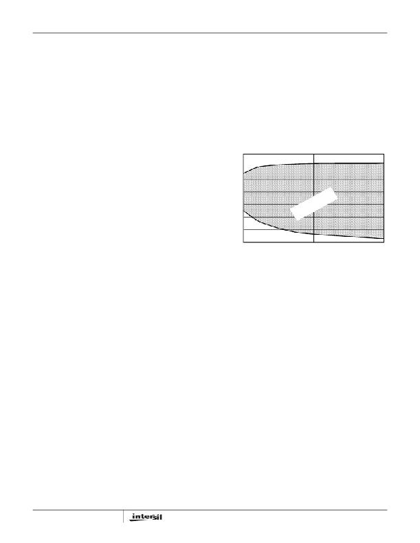
�The� output� capacitor� for� the� linear� regulator� provides� loop�
�stability.� The� linear� regulator� (OUT4)� requires� an� output�
�capacitor� characteristic� shown� in� Figure� 13� The� upper� line�
�plots� the� 45� phase� margin� with� 150mA� load� and� the� lower�
�line� is� the� 45� phase� margin� limit� with� a� 10mA� load.� Select� a�
�C� OUT4� capacitor� with� characteristic� between� the� two� limits.�
�0.7�
�0.6�
�0.5�
�0.4�
�LE� N�
�S� T� RAT�
�PE�
�PWM� Output� Capacitors�
�Modern� microprocessors� produce� transient� load� rates� above�
�10A/ns.� High� frequency� capacitors� initially� supply� the� transient�
�and� slow� the� current� load� rate� seen� by� the� bulk� capacitors.�
�The� bulk� filter� capacitor� values� are� generally� determined� by�
�0.3�
�0.2�
�0.1�
�O�
�AB� IO�
�the� ESR� (effective� series� resistance)� and� ESL� (effective�
�10�
�100�
�1000�
�series� inductance)� parameters� rather� than� actual� capacitance.�
�High� frequency� decoupling� capacitors� should� be� placed� as�
�close� to� the� power� pins� of� the� load� as� physically� possible.� Be�
�careful� not� to� add� inductance� in� the� circuit� board� wiring� that�
�could� cancel� the� usefulness� of� these� low� inductance�
�components.� Consult� with� the� manufacturer� of� the� load� on�
�specific� decoupling� requirements.�
�Use� only� specialized� low-ESR� capacitors� intended� for�
�switching� regulator� applications� for� the� bulk� capacitors.� The�
�bulk� capacitor’s� ESR� determines� the� output� ripple� voltage� and�
�CAPACITANCE� (� μ� F)�
�FIGURE� 13.� C� OUT4� OUTPUT� CAPACITOR�
�Output� Inductor� Selection�
�Each� PWM� converter� requires� an� output� inductor.� The�
�output� inductor� is� selected� to� meet� the� output� voltage� ripple�
�requirements� and� sets� the� converter’s� response� time� to� a�
�load� transient.� The� inductor� value� determines� the� converter’s�
�ripple� current� and� the� ripple� voltage� is� a� function� of� the� ripple�
�current.� The� ripple� voltage� and� current� are� approximated� by�
�the� following� equations:�
�V� IN� –� V� OUT� V� OUT�
�F� S� � L� O�
�the� initial� voltage� drop� after� a� high� slew-rate� transient.� An�
�aluminum� electrolytic� capacitor’s� ESR� value� is� related� to� the�
�case� size� with� lower� ESR� available� in� larger� case� sizes.�
�?� I� =� --------------------------------� � ----------------�
�V� IN�
�?� V� OUT� =� ?� I� � ESR�
�V� TRAN� =� ESL� � ---------------------� +� ESR� � I� TRAN�
�However,� the� equivalent� series� inductance� of� these� capacitors�
�increases� with� case� size� and� can� reduce� the� usefulness� of� the�
�capacitor� to� high� slew-rate� transient� loading.� Unfortunately,�
�ESL� is� not� a� specified� parameter.� Work� with� your� capacitor�
�supplier� and� measure� the� capacitor’s� impedance� with�
�frequency� to� select� suitable� components.� In� most� cases,�
�multiple� electrolytic� capacitors� of� small� case� size� perform�
�better� than� a� single� large� case� capacitor.� For� a� given� transient�
�load� magnitude,� the� output� voltage� transient� response� due� to�
�the� output� capacitor� characteristics� can� be� approximated� by�
�the� following� equation:�
�dI� TRAN�
�dt�
�Linear� Output� Capacitors�
�12�
�Increasing� the� value� of� inductance� reduces� the� ripple� current�
�and� voltage.� However,� the� large� inductance� values� reduce�
�the� converter’s� response� time� to� a� load� transient.�
�One� of� the� parameters� limiting� the� converter’s� response� to� a�
�load� transient� is� the� time� required� to� change� the� inductor�
�current.� Given� a� sufficiently� fast� control� loop� design,� the�
�HIP6019B� will� provide� either� 0%� or� 100%� duty� cycle� in�
�response� to� a� load� transient.� The� response� time� is� the� time�
�interval� required� to� slew� the� inductor� current� from� an� initial�
�current� value� to� the� post-transient� current� level.� During� this�
�interval� the� difference� between� the� inductor� current� and� the�
�transient� current� level� must� be� supplied� by� the� output�
�capacitors.� Minimizing� the� response� time� can� minimize� the�
�output� capacitance� required.�
�FN4587.1�
�April� 13,� 2005�
�相关PDF资料 |
PDF描述 |
|---|---|
| V375C3V3H50BL3 | CONVERTER MOD DC/DC 3.3V 50W |
| H7PXH-1510M | CABLE D-SUB - HMM15H/AE15M/X |
| ISL6534CV | IC REG 3OUT BCK/LINEAR 24EPTSSOP |
| SE15PJ-M3/85A | DIODE ESD 1.5A 600V DO-220AA |
| ECS-T1AX106R | CAP TANT 10UF 10V 20% 1411 |
相关代理商/技术参数 |
参数描述 |
|---|---|
| HIP6019BCBZ | 功能描述:电压模式 PWM 控制器 ADV DL 3PWM & DL LINER PWR CONTROL RoHS:否 制造商:Texas Instruments 输出端数量:1 拓扑结构:Buck 输出电压:34 V 输出电流: 开关频率: 工作电源电压:4.5 V to 5.5 V 电源电流:600 uA 最大工作温度:+ 125 C 最小工作温度:- 40 C 封装 / 箱体:WSON-8 封装:Reel |
| HIP6019BCBZ-T | 功能描述:电压模式 PWM 控制器 ADV DL 3PWM & DL LINER PWR CONTROL RoHS:否 制造商:Texas Instruments 输出端数量:1 拓扑结构:Buck 输出电压:34 V 输出电流: 开关频率: 工作电源电压:4.5 V to 5.5 V 电源电流:600 uA 最大工作温度:+ 125 C 最小工作温度:- 40 C 封装 / 箱体:WSON-8 封装:Reel |
| HIP6019BEVAL1 | 功能描述:电源管理IC开发工具 HIP6019B EVAL BRD FOR MB PWR MGMT RoHS:否 制造商:Maxim Integrated 产品:Evaluation Kits 类型:Battery Management 工具用于评估:MAX17710GB 输入电压: 输出电压:1.8 V |
| HIP6019CB | 制造商:Harris Corporation 功能描述: |
| HIP6019CB-T | 制造商:Rochester Electronics LLC 功能描述:- Bulk |
发布紧急采购,3分钟左右您将得到回复。