- 您现在的位置:买卖IC网 > PDF目录385382 > HIP6020A (Intersil Corporation) Advanced Dual PWM and Dual Linear Power Controller PDF资料下载
参数资料
| 型号: | HIP6020A |
| 厂商: | Intersil Corporation |
| 元件分类: | 基准电压源/电流源 |
| 英文描述: | Advanced Dual PWM and Dual Linear Power Controller |
| 中文描述: | 先进的双PWM和线性双电源控制器 |
| 文件页数: | 12/16页 |
| 文件大小: | 192K |
| 代理商: | HIP6020A |
4-12
gain. Check the compensation gain at F
P2
with the capabilities
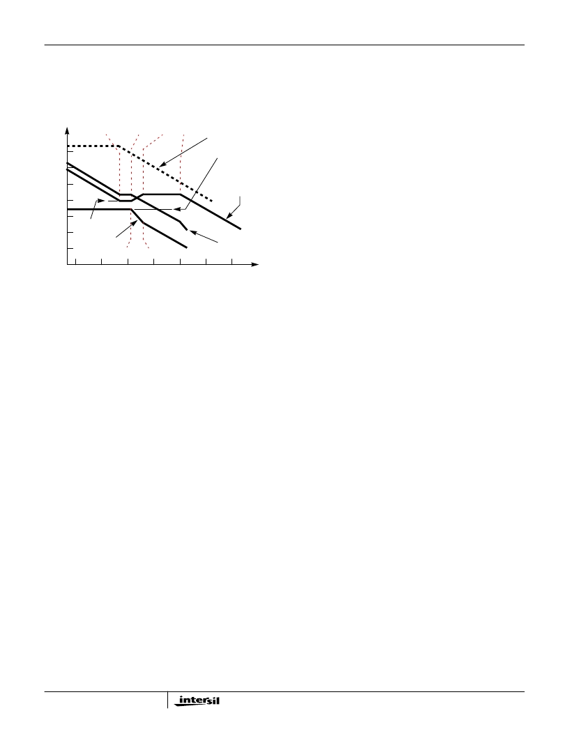
of the error amplifier. The Closed Loop Gain is constructed on
the log-log graph of Figure 12 by adding the Modulator Gain (in
dB) to the Compensation Gain (in dB). This is equivalent to
multiplying the modulator transfer function to the compensation
transfer function and plotting the gain.
The compensation gain uses external impedance networks
Z
FB
and Z
IN
to provide a stable, high bandwidth (BW) overall
loop. A stable control loop has a gain crossing with
-20dB/decade slope and a phase margin greater than
45 degrees. Include worst case component variations when
determining phase margin.
PWM2 Controller Feedback Compensation
To reduce the number of external small-signal components
required by a typical application, the standard PWM
controller is internally stabilized. The only stability criteria
that needs to be met relates the minimum value of the output
inductor to the equivalent ESR of the output capacitor bank,
as shown in the following equation:
where
L
OUT(MIN)
- minimum output inductor value at full output
current
ESR
OUT
- equivalent ESR of the output capacitor bank
BW - desired converter bandwidth (not to exceed 0.25 to
0.30 of the switching frequency)
The design procedure for this output should follow the
following steps:
1. Choosenumberandtypeofoutputcapacitorstomeetthe
output transient requirements based on the dynamic
loading characteristics of the output.
2. Determine the equivalent ESR of the output capacitor
bank and calculate minimum output inductor value.
3. Verifythatchoseninductormeetsthisminimumvaluecrite-
ria (at full output load). As inductors tend to saturate as the
currentincreases,itisrecommendedthechosenoutputin-
ductor be no more than 30% saturated at full output load.
Oscillator Synchronization
The PWM controllers use a triangle wave for comparison
with the error amplifier output to provide a pulse-width
modulated signal. Should the output voltage of the two
converters be programmed close to each other, then cross-
talk between the converters could cause non-uniform
PHASE pulse-widths and increased output voltage ripple.
The HIP6020A avoids this problem by appropriately
synchronizing the two converters for 1.5V AGP output
voltage setting. Thus, for core output voltage settings less
than 2.4V, PWM1 operates out of phase with PWM2.
Component Selection Guidelines
Output Capacitor Selection
The output capacitors for each output have unique
requirements. In general the output capacitors should be
selected to meet the dynamic regulation requirements.
Additionally, the PWM converters require an output capacitor
to filter the current ripple. The load transient for the
microprocessor core requires high quality capacitors to
supply the high slew rate (di/dt) current demands.
PWM Output Capacitors
Modern microprocessors produce transient load rates
above 1A/ns. High frequency capacitors initially supply the
transient current and slow the load rate-of-change seen by
the bulk capacitors. The bulk filter capacitor values are
generally determined by the ESR (effective series
resistance) and voltage rating requirements rather than
actual capacitance requirements.
High frequency decoupling capacitors should be placed as
close to the power pins of the load as physically possible. Be
careful not to add inductance in the circuit board wiring that
could cancel the usefulness of these low inductance
components. Consult with the manufacturer of the load on
specific decoupling requirements.
Use only specialized low-ESR capacitors intended for
switching-regulator applications for the bulk capacitors. The
bulk capacitor’s ESR determines the output ripple voltage and
the initial voltage drop following a high slew-rate transient’s
edge. An aluminum electrolytic capacitor’s ESR value is
related to the case size with lower ESR available in larger
case sizes. However, the equivalent series inductance (ESL)
of these capacitors increases with case size and can reduce
the usefulness of the capacitor to high slew-rate transient
loading. Unfortunately, ESL is not a specified parameter. Work
with your capacitor supplier and measure the capacitor’s
impedance with frequency to select a suitable component. In
most cases, multiple electrolytic capacitors of small case size
perform better than a single large case capacitor.
100
80
60
40
20
0
-20
-40
-60
F
P1
F
Z2
10M
1M
100K
10K
1K
100
10
OPEN LOOP
ERROR AMP GAIN
F
Z1
F
P2
F
LC
F
ESR
COMPENSATION
GAIN
G
FREQUENCY (Hz)
MODULATOR
GAIN
FIGURE 9. ASYMPTOTIC BODE PLOT OF CONVERTER GAIN
CLOSED LOOP
GAIN
20
P
–
-----------------
log
20
-------
log
L
OUT MIN
)
ESR
10
1.75
×
------------------------------------------------
=
HIP6020A
相关PDF资料 |
PDF描述 |
|---|---|
| HIP6020ACB | Advanced Dual PWM and Dual Linear Power Controller |
| HIP6020EVAL1 | Advanced Dual PWM and Dual Linear Power Controller |
| HIP6020 | FPGA - 100000 SYSTEM GATE 2.5 VOLT - NOT RECOMMENDED for NEW DESIGN |
| HIP6020CB | Advanced Dual PWM and Dual Linear Power Controller |
| HIP6301VCBZ-T | 100000 SYSTEM GATE 1.8 VOLT FPGA - NOT RECOMMENDED for NEW DESIGN |
相关代理商/技术参数 |
参数描述 |
|---|---|
| HIP6020A_01 | 制造商:INTERSIL 制造商全称:Intersil Corporation 功能描述:Advanced Dual PWM and Dual Linear Power Controller |
| HIP6020ACB | 制造商:Intersil Corporation 功能描述: |
| HIP6020ACB WAF | 制造商:Harris Corporation 功能描述: |
| HIP6020ACB-T | 制造商:Rochester Electronics LLC 功能描述:DUAL PWM AND 2 LINEAR CONTROLLER W/O VID=11111 SHUTDOWN - Tape and Reel |
| HIP6020CB | 制造商:Rochester Electronics LLC 功能描述:DUAL PWM AND 2 LINEAR CONTROLLER - Bulk |
发布紧急采购,3分钟左右您将得到回复。