- 您现在的位置:买卖IC网 > PDF目录371821 > HIP6028 (Intersil Corporation) Advanced PWM and Dual Linear Power Control with Integrated ACPI Support Interface PDF资料下载
参数资料
| 型号: | HIP6028 |
| 厂商: | Intersil Corporation |
| 元件分类: | 基准电压源/电流源 |
| 英文描述: | Advanced PWM and Dual Linear Power Control with Integrated ACPI Support Interface |
| 中文描述: | 先进的双PWM和线性电源控制集成接口ACPI支持 |
| 文件页数: | 10/16页 |
| 文件大小: | 140K |
| 代理商: | HIP6028 |
2-320
Application Guidelines
Soft-Start Interval
Initially,thesoft-startfunctionclampstheerroramplifier’soutput
of the PWM converter. After the output voltage increases to
approximately 80% of the set value, the reference input of the
erroramplifierisclampedtoavoltageproportionaltotheSSpin
voltage. The linear controller output follows a similar start-up
sequence. The integrated linear regulator’s soft-start is
independent of C
SS
, its ramp-up time being dependent on the
230mA current limit and the size of the output capacitor. The
resulting output voltage sequence is shown in Figure 6.
The soft-start function controls the output voltage rate of rise
to limit the current surge at start-up. The soft-start interval is
programmed by the soft-start capacitor, C
SS
. Programming
a faster soft-start interval increases the peak surge current.
The peak surge current occurs during the initial output
voltage rise to 80% of the set value.
Shutdown
The PWM output does not switch until the soft-start voltage
exceeds the oscillator’s valley voltage. Additionally, the linear
controller and PWM’s error amplifiers inputs are clamped to
the soft-start voltage. Applying a logic ‘high’ signal on the
SD1&3 pin turns off the GTL (V
OUT3
) and core PWM
(V
OUT1
) regulators and discharges the soft-start capacitor.
Releasing, or applying a logic ‘low’ on the SD1&3 pin allows
the GTL and core voltages to undergo a soft-start ramp-up
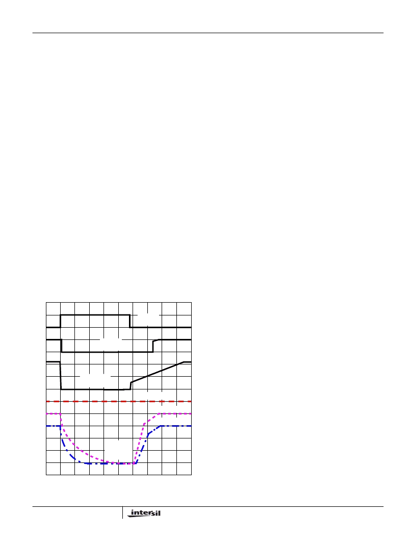
to their preset levels. Figure 10 exemplifies such output
sequencing resulting from SD1&3 pin toggling (S3 power-
saving sleep mode cycling).
Toggling the SD1&3 pin does not affect V
OUT2
(2.5V), which
remains operational as long as the input voltages are above
their POR levels and output current rating is not exceeded.
The ‘11111’ VID code resulting in an INHIBIT, as shown in
Table 1, disables the entire IC (all outputs).
Layout Considerations
MOSFETs switch very fast and efficiently. The speed with
which the current transitions from one device to another
causes voltage spikes across the interconnecting
impedances and parasitic circuit elements. The voltage
spikes can degrade efficiency, radiate noise into the circuit,
and lead to device over-voltage stress. Careful component
layout and printed circuit design minimizes the voltage
spikes in the converter. Consider, as an example, the turn-off
transition of the upper PWM MOSFET. Prior to turn-off, the
upper MOSFET is carrying the full load current. During the
turn-off, current stops flowing in the upper MOSFET and is
picked up by the lower MOSFET (and/or parallel Schottky
diode). Any inductance in the switched current path
generates a large voltage spike during the switching interval.
Careful component selection, tight layout of the critical
components, and short, wide circuit traces minimize the
magnitude of voltage spikes. Contact Intersil for evaluation
board drawings of the component placement and printed
circuit board.
There are two sets of critical components in a DC-DC
converter using a HIP6028 controller. The power
components are the most critical because they switch large
amounts of energy. The critical small signal components
connect to sensitive nodes or supply critical by-passing
current.
The power components should be placed first. Locate the
input capacitors close to the power switches. Minimize the
length of the connections between the input capacitors and
the power switches. Locate the output inductor and output
capacitors between the MOSFETs and the load. Locate the
PWM controller close to the MOSFETs.
The critical small signal components include the bypass
capacitor for VCC and the soft-start capacitor, C
SS
. Locate
these components close to their connecting pins on the
control IC. Minimize any leakage current paths from SS node
because the internal current source is only 11
μ
A.
FIGURE 10. POWER-SAVING SHUTDOWN SEQUENCE DETAIL
0V
0V
0V
TIME
PGOOD
(2V/DIV)
SOFT-START
(2V/DIV)
OUTPUT
VOLTAGES
(0.5V/DIV)
V
OUT1
(DAC = 2V)
V
OUT3
( = 1.5V)
0V
V
OUT2
( = 2.5V)
SD1&3
(5V/DIV)
HIP6028
相关PDF资料 |
PDF描述 |
|---|---|
| HIP6028CB | Advanced PWM and Dual Linear Power Control with Integrated ACPI Support Interface |
| HIP6303CB-T | Microprocessor CORE Voltage Regulator Multi-Phase Buck PWM Controller |
| HIP6303 | Microprocessor CORE Voltage Regulator Multi-Phase Buck PWM Controller(微处理器核心电压稳压多相冲跳脉宽调制控制器) |
| HIP6303CB | Microprocessor CORE Voltage Regulator Multi-Phase Buck PWM Controller |
| HIP6303EVAL1 | Microprocessor CORE Voltage Regulator Multi-Phase Buck PWM Controller |
相关代理商/技术参数 |
参数描述 |
|---|---|
| HIP6028CB | 制造商:Rochester Electronics LLC 功能描述:- Bulk |
| HIP6028CB WAF | 制造商:Harris Corporation 功能描述: |
| HIP6028EVAL1 | 制造商:INTERSIL 制造商全称:Intersil Corporation 功能描述:Advanced PWM and Dual Linear Power Control with Integrated ACPI Support Interface |
| HIP6034CB | 制造商:未知厂家 制造商全称:未知厂家 功能描述:Analog IC |
| HIP6034CB-T | 制造商:未知厂家 制造商全称:未知厂家 功能描述:Analog IC |
发布紧急采购,3分钟左右您将得到回复。