- 您现在的位置:买卖IC网 > PDF目录371821 > HIP6304CB-T (INTERSIL CORP) Microprocessor CORE Voltage Regulator Multi-Phase Buck PWM Controller PDF资料下载
参数资料
| 型号: | HIP6304CB-T |
| 厂商: | INTERSIL CORP |
| 元件分类: | 稳压器 |
| 英文描述: | Microprocessor CORE Voltage Regulator Multi-Phase Buck PWM Controller |
| 中文描述: | SWITCHING CONTROLLER, 1500 kHz SWITCHING FREQ-MAX, PDSO16 |
| 封装: | PLASTIC, MS-012AC, SOIC-16 |
| 文件页数: | 12/14页 |
| 文件大小: | 176K |
| 代理商: | HIP6304CB-T |
12
the phase nodes. Use the remaining printed circuit layers for
small signal wiring. The wiring traces from the driver IC to the
MOSFET gate and source should be sized to carry at least
one ampere of current.
Component Selection Guidelines
Output Capacitor Selection
The output capacitor is selected to meet both the dynamic
load requirements and the voltage ripple requirements. The
load transient for the microprocessor CORE is characterized
by high slew rate (di/dt) current demands. In general,
multiple high quality capacitors of different size and dielectric
are paralleled to meet the design constraints.
Modern microprocessors produce severe transient load rates.
High frequency capacitors supply the initially transient current
and slow the load rate-of-change seen by the bulk capacitors.
The bulk filter capacitor values are generally determined by
the ESR (effective series resistance) and voltage rating
requirements rather than actual capacitance requirements.
High frequency decoupling capacitors should be placed as
close to the power pins of the load as physically possible. Be
careful not to add inductance in the circuit board wiring that
could cancel the usefulness of these low inductance
components. Consult with the manufacturer of the load on
specific decoupling requirements.
Use only specialized low-ESR capacitors intended for
switching-regulator applications for the bulk capacitors. The
bulk capacitor’s ESR determines the output ripple voltage
and the initial voltage drop following a high slew-rate
transient’s edge. In most cases, multiple capacitors of small
case size perform better than a single large case capacitor.
Bulk capacitor choices include aluminum electrolytic, OS-
Con, Tantalum and even ceramic dielectrics. An aluminum
electrolytic capacitor’s ESR value is related to the case size
with lower ESR available in larger case sizes. However, the
equivalent series inductance (ESL) of these capacitors
increases with case size and can reduce the usefulness of
the capacitor to high slew-rate transient loading.
Unfortunately, ESL is not a specified parameter. Consult the
capacitor manufacturer and measure the capacitor’s
impedance with frequency to select a suitable component.
Output Inductor Selection
One of the parameters limiting the converter’s response to a
load transient is the time required to change the inductor
current. Small inductors in a multi-phase converter reduces
the response time without significant increases in total ripple
current.
The output inductor of each power channel controls the
ripple current. The control IC is stable for channel ripple
current (peak-to-peak) up to twice the average current. A
single channel’s ripple current is approximately:
The current from multiple channels tend to cancel each other
and reduce the total ripple current. Figure 12 gives the total
ripple current as a function of duty cycle, normalized to the
parameter
at zero duty cycle. To determine the
total ripple current from the number of channels and the duty
cycle, multiply the y-axis value by
.
Small values of output inductance can cause excessive power
dissipation. The HIP6303 is designed for stable operation for
ripple currents up to twice the load current. However, for this
condition, the RMS current is 115% above the value shown in
the following MOSFET Selection and Considerations section.
With all else fixed, decreasing the inductance could increase
the power dissipated in the MOSFETs by 30%.
I
V
-------------------------------
V
–
SW
V
IN
---------------
×
=
Vo
(
)
L F
S
(
)
Vo
(
)
LxF
SW
(
)
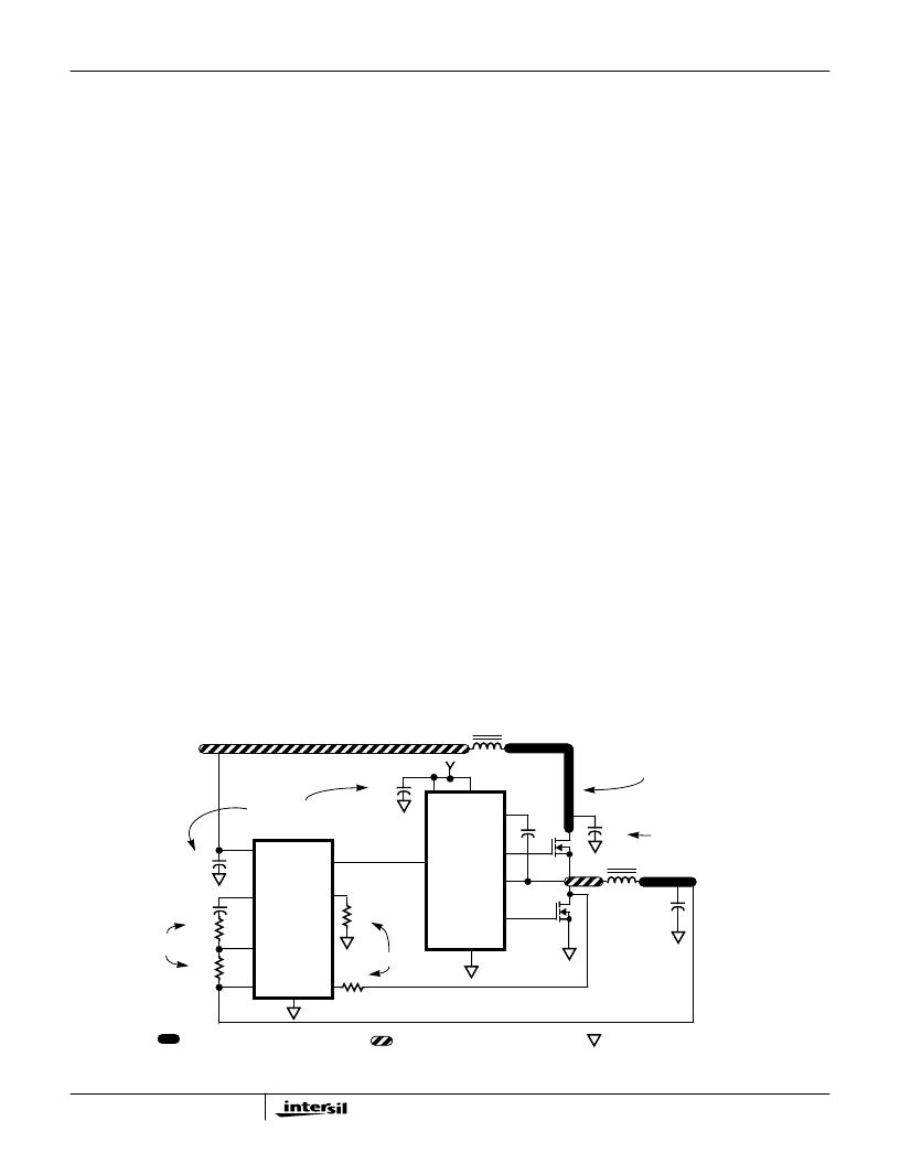
V
CORE
+12V
VIA CONNECTION TO GROUND PLANE
ISLAND ON POWER PLANE LAYER
ISLAND ON CIRCUIT PLANE LAYER
L
O1
C
OUT
C
IN
+5V
IN
PHASE
VCC
USE INDIVIDUAL METAL RUNS
FOR EACH CHANNEL TO HELP
COMP
HIP6304
PWM
R
T
R
IN
R
FB
C
BP
FB
VSEN
ISEN
R
SEN
HIP6601
C
BOOT
C
BP
C
T
V
CC
FS/DIS
PVCC
LOCATE NEXT TO IC PIN
LOCATE NEXT
TO FB PIN
LOCATE NEXT TO IC PIN(S)
ISOLATE OUTPUT STAGES
LOCATE NEAR TRANSISTOR
FIGURE 11. PRINTED CIRCUIT BOARD POWER PLANES AND ISLANDS
LEGEND
HIP6304
相关PDF资料 |
PDF描述 |
|---|---|
| HIP6304 | Microprocessor CORE Voltage Regulator Multi-Phase Buck PWM Controller(微处理器核心电压稳压器多相PWM控制电路) |
| HIP6304CB | 150000 SYSTEM GATE 2.5 VOLT FPGA - NOT RECOMMENDED for NEW DESIGN |
| HIP6304EVAL1 | Microprocessor CORE Voltage Regulator Multi-Phase Buck PWM Controller |
| HIP6500B | Multiple Linear Power Controller with ACPI Control Interface |
| HIP6500BCB | Multiple Linear Power Controller with ACPI Control Interface |
相关代理商/技术参数 |
参数描述 |
|---|---|
| HIP6304EVAL1 | 制造商:INTERSIL 制造商全称:Intersil Corporation 功能描述:Microprocessor CORE Voltage Regulator Multi-Phase Buck PWM Controller |
| HIP6311 | 制造商:INTERSIL 制造商全称:Intersil Corporation 功能描述:Microprocessor CORE Voltage Regulator Multi-Phase Buck PWM Controller |
| HIP6311_04 | 制造商:INTERSIL 制造商全称:Intersil Corporation 功能描述:Microprocessor CORE Voltage Regulator Multi-Phase Buck PWM Controller |
| HIP6311A | 制造商:INTERSIL 制造商全称:Intersil Corporation 功能描述:Microprocessor CORE Voltage Regulator Multi-Phase Buck PWM Controller |
| HIP6311ACB | 功能描述:IC REG CTRLR BUCK PWM 20-SOIC RoHS:否 类别:集成电路 (IC) >> PMIC - 稳压器 - DC DC 切换控制器 系列:- 标准包装:4,000 系列:- PWM 型:电压模式 输出数:1 频率 - 最大:1.5MHz 占空比:66.7% 电源电压:4.75 V ~ 5.25 V 降压:是 升压:无 回扫:无 反相:无 倍增器:无 除法器:无 Cuk:无 隔离:无 工作温度:-40°C ~ 85°C 封装/外壳:40-VFQFN 裸露焊盘 包装:带卷 (TR) |
发布紧急采购,3分钟左右您将得到回复。