- 您现在的位置:买卖IC网 > Datasheet目录327 > HIP6521EVAL1 (Intersil)EVALUATION BOARD HIP6521 Datasheet资料下载
参数资料
| 型号: | HIP6521EVAL1 |
| 厂商: | Intersil |
| 文件页数: | 1/12页 |
| 文件大小: | 0K |
| 描述: | EVALUATION BOARD HIP6521 |
| 标准包装: | 1 |
| 主要目的: | DC/DC,LDO 步降 |
| 输出及类型: | 4,非隔离 |
| 输出电压: | 2.5V,1.5V,1.8V,2.5V |
| 电流 - 输出: | 8A,3A,3A,1A |
| 输入电压: | 3.3V,5V,12V |
| 稳压器拓扑结构: | 降压 |
| 频率 - 开关: | 300kHz |
| 板类型: | 完全填充 |
| 已供物品: | 板 |
| 已用 IC / 零件: | HIP6521 |
�� �
�
�Peripheral� Power� Controller� for� Pentium?� 4�
�TM�
�Computer� Systems� (HIP6521EVAL1)�
�Application� Note�
�March� 2001�
�AN9908.2�
�Author:� Bogdan� M.� Duduman�
�Introduction�
�The� progress� of� the� advanced� computing� cores� coming� from�
�microprocessor� manufacturers� such� as� Intel� and� AMD� have�
�necessitated� a� change� in� the� topology� of� the� switching�
�regulators� traditionally� used� to� power� these� processor� cores.�
�Multiphase� buck� regulators� have� proven� to� be� the� topology�
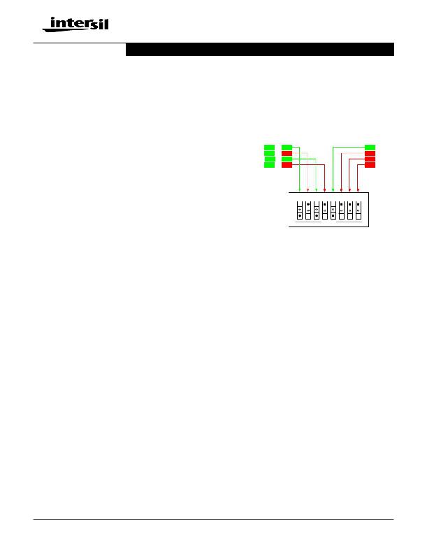
�Each� output� can� thus� be� turned� off� or� kept� running� in� S3�
�and/or� S5� states,� with� corresponding� consequences.� For�
�initial� evaluation,� we� recommend� closing� positions� 2,� 4,� and�
�6-8� (see� Figure� 1� for� detail).� Unless� otherwise� speci?ed,� this�
�recommended� SW3� con?guration� was� employed� throughout�
�testing� of� the� board� described� in� this� application� note.�
�of� choice� for� such� high-current� applications.� However,� the�
�distributed� power� system� architecture� of� these� computers�
�continue� to� have� a� need� for� other� sub-system� speci?c�
�voltages.� The� HIP6521� was� created� to� complement� a�
�multiphase� buck� controller� in� creating� a� complete� power�
�VOUT1�
�VOUT2�
�VOUT3�
�VOUT4�
�S0�
�ON�
�ON�
�ON�
�ON�
�S3�
�ON�
�OFF�
�ON�
�OFF�
�S5�
�ON�
�OFF�
�OFF�
�OFF�
�solution� for� the� typical� Pentium� 4� system.� Athlon-class�
�processor� based� systems� (AMD)� may� also� bene?t� from� the�
�HIP6521.� [1]�
�1�
�2�
�3�
�4�
�5�
�6�
�7�
�8�
�The� HIP6521EVAL1� evaluation� board� embodies� a� 4-output�
�regulator� solution� targeted� at� supplying� power� to� the� system�
�memory� (2.5V),� system� clock� (2.5V),� ICH/MCH� chip� set� core�
�(1.8V),� and� the� 4X� AGP� video� (1.5V),� with� provisions� for�
�ACPI� power� management� implementation.� [2]�
�Quick� Start� Evaluation�
�Important!�
�To� facilitate� the� evaluation� of� the� HIP6521� in� a� typical� setting,�
�the� HIP6521EVAL1� was� designed� to� be� powered� primarily�
�from� an� ATX� supply.� However,� the� board� does� have� hook-up�
�turret� terminals� that� allow� it� to� be� piggy-backed� in� an� actual�
�computer� system,� or� be� powered� from� standard� laboratory�
�power� supplies�
�If� an� ATX� power� supply� is� used� to� power� the� board� (using� the�
�on-board� 20-pin� connector),� remember� that� regulation� of�
�most� ATX� supplies� is� generally� dependent� on� the� presence�
�of� a� DC� load� on� the� main� 5V� output.� Therefore,� for� best�
�results,� have� a� 5� ?� /25W-50W� power� resistor� connected� to�
�the� 5V� output� of� the� ATX� supply� (take� necessary�
�precautions,� as� the� resistor� may� get� very� hot).� [3]�
�Circuit� Setup�
�Before� connecting� an� input� supply� to� the� board,� consult� the�
�circuit� schematic� and� familiarize� yourself� with� the� various�
�connection� options� offered� by� the� HIP6521EVAL1.�
�?� Set� Switches�
�Ensure� the� ‘ATX� ON’� (� SW1� )� switch� is� in� the� off� position�
�(away� from� ‘ATX� ON’� marking)� and� ‘S3/S5’� (� SW2� )� switch� is�
�in� the� middle� position� (away� from� ‘S3’� or� ‘S5’� marking).�
�SW3� helps� with� the� control� of� the� various� outputs� in� ACPI�
�shutdown� states.� To� avoid� having� the� powerful� output� drives�
�(of� the� regulators� that� have� to� be� off� in� certain� sleep� states)�
�hold� the� outputs� within� regulation,� they� have� to� be� actively�
�kept� off� by� pulling� the� corresponding� FB� pins� above� 1.25V.�
�OPEN�
�FIGURE� 1.� SW3� DETAIL� (RECOMMENDED� INITIAL�
�CONFIGURATION)� -� SLEEP� STATES� SUPPORT�
�?� Set� Jumpers� JP1-4�
�JP1� and� JP3� select� the� on-board� input� voltage� for� the� linear�
�pass� elements� corresponding� to� the� VOUT3� and� VOUT4�
�outputs,� respectively.� One� recommended� con?guration� for�
�initial� evaluation� is� with� JP1� populated� in� the� ‘2.5VIN’�
�position� and� JP3� in� the� ‘3.3VIN’� position.�
�JP2� and� JP4� select� the� ‘+3.3VDUAL’� as� the� input� for� the� two�
�linear� pass� elements� mentioned� above.� If� an� external�
�3.3VDUAL� source� is� supplied,� either� pass� element� (Q4� and/or�
�Q5)� may� be� powered� from� this� source� by� moving� the� respective�
�header� jumper� from� JP1� or� JP3,� onto� JP2� or� JP4,� respectively.�
�?� Hookup� Guide� Using� Standard� Bench� Supplies�
�Connect� a� 5V,� 16A� supply� to� the� +5VDUAL� input� and� a� 3.3V,�
�4A,� supply� to� the� +3.3VIN� input.� Another� 3.3V,� 4A� supply� may�
�be� needed� for� the� optional� +3.3VDUAL� input� if� either� JP2� or�
�JP4� are� populated.� Connect� typical� loads� to� all� the� evaluation�
�board’s� outputs.� Consult� Table� 1� for� maximum� loads�
�supported� by� the� design� of� the� in� the� configuration� received;�
�consult� the� ‘Modifications’� section� for� information� on� modifying�
�the� evaluation� board� to� meet� your� special� needs.�
�?� Hookup� Guide� Using� a� Standard� ATX� Supply�
�Connect� the� 20-pin� ATX� connector� to� the� on-board� J1� mating�
�connector.� Connect� typical� loads� to� all� the� evaluation� board’s�
�outputs.� Consult� Table� 1� for� maximum� loads� supported� by�
�the� design� of� the� in� the� con?guration� received;� consult� the�
�‘Modi?cations’� section� for� information� on� modifying� the�
�evaluation� board� to� meet� your� special� needs.�
�1�
�1-888-INTERSIL� or� 321-724-7143�
�|�
�Pentium?� is� a� registered� trademark� of� Intel� Corporation.�
�Intersil� and� Design� is� a� trademark� of� Intersil� Americas� Inc.�
�Copyright� ?� Intersil� Americas� Inc.� 2001,� All� Rights� Reserved�
�相关PDF资料 |
PDF描述 |
|---|---|
| HIP6602BCR-T | IC DRVR MOSF 2CH SYC BUCK 16-QFN |
| HIP6603BCBZ | IC DRIVER MOSFET SYNC BUCK 8SOIC |
| HS0005KCU04H | EMULATOR E10A-USB SUPERH RISC |
| HT1010SAT3 | SURGE SUPPRESS 15A 10OUT 10'C |
| HT10DBS | SURGE SUPPRESS 12A 10OUT 8'CORD |
相关代理商/技术参数 |
参数描述 |
|---|---|
| HIP6601 | 制造商:INTERSIL 制造商全称:Intersil Corporation 功能描述:Synchronous-Rectified Buck MOSFET Drivers |
| HIP6601_04 | 制造商:INTERSIL 制造商全称:Intersil Corporation 功能描述:Synchronous-Rectified Buck MOSFET Drivers |
| HIP6601A | 制造商:INTERSIL 制造商全称:Intersil Corporation 功能描述:Synchronous Rectified Buck MOSFET Drivers |
| HIP6601ACB | 制造商:INTERSIL 制造商全称:Intersil Corporation 功能描述:Synchronous Rectified Buck MOSFET Drivers |
| HIP6601ACB-T | 制造商:Rochester Electronics LLC 功能描述:- Bulk |
发布紧急采购,3分钟左右您将得到回复。