- 您现在的位置:买卖IC网 > PDF目录299176 > HK10051N2S (TAIYO YUDEN CO LTD) 1 ELEMENT, 0.0012 uH, FERRITE-CORE, GENERAL PURPOSE INDUCTOR, SMD PDF资料下载
参数资料
| 型号: | HK10051N2S |
| 厂商: | TAIYO YUDEN CO LTD |
| 元件分类: | 通用定值电感 |
| 英文描述: | 1 ELEMENT, 0.0012 uH, FERRITE-CORE, GENERAL PURPOSE INDUCTOR, SMD |
| 封装: | CHIP, 0402, ROHS COMPLIANT |
| 文件页数: | 13/21页 |
| 文件大小: | 755K |
| 代理商: | HK10051N2S |
mlci0109_reli-PRP15
mlci0109_reli_e-01
■ PRECAUTIONS
*This catalog contains the typical specication only due to the limitation of space. When you consider the purchase of our products, please check our specication.
For details of each product (characteristics graph, reliability information, precautions for use, and so on), see our Web site (http://www.ty-top.com/) or CD catalogs.
Precautions on the use of Multilayer chip Inductors, Multilayer chip inductors for high frequency, Multilayer ferrite chip beads
4. Soldering
Precautions
◆Selection of Flux
1. Since ux may have a signicant effect on the performance of inductors, it is necessary to verify the following conditions prior to use;
(1)Flux used should be with less than or equal to 0.1 wt%(Chlorine conversion method)of halogenated content. Flux having a strong acidity content should
not be applied.
(2)When soldering inductors on the board, the amount of ux applied should be controlled at the optimum level.
(3)When using water-soluble ux, special care should be taken to properly clean the boards.
◆Soldering
1. Temperature, time, amount of solder, etc. are specied in accordance with the following recommended conditions, and please contact us about peak tem-
and please contact us about peak tem-
perature when you use lead-free paste.
Technical
consider-
ations
◆Selection of Flux
1-1. When too much halogenated substance(Chlorine, etc.)content is used to activate the ux, or highly acidic ux is used, an excessive amount of residue
after soldering may lead to corrosion of the terminal electrodes or degradation of insulation resistance on the surface of the Inductor.
1-2. Flux is used to increase solderability in ow soldering, but if too much is applied, a large amount of ux gas may be emitted and may detrimentally affect
solderability. To minimize the amount of ux applied, it is recommended to use a ux-bubbling system.
1-3. Since the residue of water-soluble ux is easily dissolved by water content in the air, the residue on the surface of Inductor in high humidity conditions may
cause a degradation of insulation resistance and therefore affect the reliability of the components. The cleaning methods and the capability of the machines
used should also be considered carefully when selecting water-soluble ux.
◆Soldering
1-1. Preheating when soldering
Heating: Chip inductor components should be preheated to within 100 to 130℃ of the soldering. Cooling: The temperature difference between the
components and cleaning process should not be greater than 100℃.
Chip inductors are susceptible to thermal shock when exposed to rapid or concentrated heating or rapid cooling. Therefore, the soldering process must be
conducted with a great care so as to prevent malfunction of the components due to excessive thermal shock.
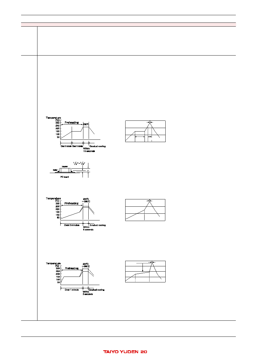
Recommended conditions for soldering
[Reow soldering]
Temperature prole
Peak 260
max
10 sec max
Pb free soldering
Peak 260
max
10 sec max
Ceramic chip components should be preheated to
within 100 to 130
of the soldering.
Assured to be reow soldering for 2 times.
Ceramic chip components should be preheated to
within 100 to 130
of the soldering.
Assured to be wave soldering for 1 time.
Except for reow soldering type.
T190
3216Type max ,
130
3225
Type ming
It is recommended to use 20W soldering iron and
the tip is 1 or less.
The soldering iron should not directly touch the
components.
Assured to be soldering iron for 1 time.
Note: The above proles are the maximum allowable
soldering condition, therefore these proles are
not always recommended.
Temperature
300
200
100
0
Temperature
300
200
100
0
Temperature
400
300
200
100
0
Preheating
150
60 sec min
Gradually
cooling
Gradually
cooling
Gradually
cooling
Heating above 230
40 sec max
Preheating
150
120 sec min
350
max
3 sec max
60 sec min
Caution
1. The ideal condition is to have solder mass(llet)controlled to 1/2 to 1/3 of the thickness of the inductor, as shown below:
2. Because excessive dwell times can detrimentally affect solderability, soldering duration should be kept as close to recommended times as possible.
[Wave soldering]
Temperature prole
Peak 260
max
10 sec max
Pb free soldering
Peak 260
max
10 sec max
Ceramic chip components should be preheated to
within 100 to 130
of the soldering.
Assured to be reow soldering for 2 times.
Ceramic chip components should be preheated to
within 100 to 130
of the soldering.
Assured to be wave soldering for 1 time.
Except for reow soldering type.
T190
3216Type max ,
130
3225
Type ming
It is recommended to use 20W soldering iron and
the tip is 1 or less.
The soldering iron should not directly touch the
components.
Assured to be soldering iron for 1 time.
Note: The above proles are the maximum allowable
soldering condition, therefore these proles are
not always recommended.
Temperature
300
200
100
0
Temperature
300
200
100
0
Temperature
400
300
200
100
0
Preheating
150
60 sec min
Gradually
cooling
Gradually
cooling
Gradually
cooling
Heating above 230
40 sec max
Preheating
150
120 sec min
350
max
3 sec max
60 sec min
Caution
1. Make sure the inductors are preheated sufciently.
2. The temperature difference between the inductor and melted solder should not be greater than 100 to 130℃.
3. Cooling after soldering should be as gradual as possible.
4. Wave soldering must not be applied to the inductors designated as for reow soldering only.
[Hand soldering]
Temperature prole
Peak 260
max
10 sec max
Pb free soldering
Peak 260
max
10 sec max
Ceramic chip components should be preheated to
within 100 to 130
of the soldering.
Assured to be reow soldering for 2 times.
Ceramic chip components should be preheated to
within 100 to 130
of the soldering.
Assured to be wave soldering for 1 time.
Except for reow soldering type.
T190
3216Type max ,
130
3225
Type ming
It is recommended to use 20W soldering iron and
the tip is 1 or less.
The soldering iron should not directly touch the
components.
Assured to be soldering iron for 1 time.
Note: The above proles are the maximum allowable
soldering condition, therefore these proles are
not always recommended.
Temperature
300
200
100
0
Temperature
300
200
100
0
Temperature
400
300
200
100
0
Preheating
150
60 sec min
Gradually
cooling
Gradually
cooling
Gradually
cooling
Heating above 230
40 sec max
Preheating
150
120 sec min
350
max
3 sec max
60 sec min
Caution
1. Use a 20W soldering iron with a maximum tip diameter of 1.0 mm.
2. The soldering iron should not directly touch the inductor.
相关PDF资料 |
PDF描述 |
|---|---|
| HK1005R10K | 1 ELEMENT, 0.1 uH, FERRITE-CORE, GENERAL PURPOSE INDUCTOR, SMD |
| HK100582NK | 1 ELEMENT, 0.082 uH, FERRITE-CORE, GENERAL PURPOSE INDUCTOR, SMD |
| HK100568NK | 1 ELEMENT, 0.068 uH, FERRITE-CORE, GENERAL PURPOSE INDUCTOR, SMD |
| HK10058N2K | 1 ELEMENT, 0.0082 uH, FERRITE-CORE, GENERAL PURPOSE INDUCTOR, SMD |
| HK10055N6K | 1 ELEMENT, 0.0056 uH, FERRITE-CORE, GENERAL PURPOSE INDUCTOR, SMD |
相关代理商/技术参数 |
参数描述 |
|---|---|
| HK10051N2S-T | 功能描述:固定电感器 INDCTR HIFREQ MLTLYR 0402 1.20.3nH RoHS:否 制造商:AVX 电感:10 uH 容差:20 % 最大直流电流:1 A 最大直流电阻:0.075 Ohms 工作温度范围:- 40 C to + 85 C 自谐振频率:38 MHz Q 最小值:40 尺寸:4.45 mm W x 6.6 mm L x 2.92 mm H 屏蔽:Shielded 端接类型:SMD/SMT 封装 / 箱体:6.6 mm x 4.45 mm |
| HK10051N2S-T | 制造商:TAIYO YUDEN 功能描述:Inductor Series:LG HK 制造商:TAIYO YUDEN 功能描述:INDUCTOR |
| HK-1005-1N2STK | 功能描述:固定电感器 1.2nH 300mA 0.3nH RoHS:否 制造商:AVX 电感:10 uH 容差:20 % 最大直流电流:1 A 最大直流电阻:0.075 Ohms 工作温度范围:- 40 C to + 85 C 自谐振频率:38 MHz Q 最小值:40 尺寸:4.45 mm W x 6.6 mm L x 2.92 mm H 屏蔽:Shielded 端接类型:SMD/SMT 封装 / 箱体:6.6 mm x 4.45 mm |
| HK10051N5S-T | 功能描述:固定电感器 INDCTR HIFREQ MLTLYR 0402 1.50.3nH RoHS:否 制造商:AVX 电感:10 uH 容差:20 % 最大直流电流:1 A 最大直流电阻:0.075 Ohms 工作温度范围:- 40 C to + 85 C 自谐振频率:38 MHz Q 最小值:40 尺寸:4.45 mm W x 6.6 mm L x 2.92 mm H 屏蔽:Shielded 端接类型:SMD/SMT 封装 / 箱体:6.6 mm x 4.45 mm |
| HK-1005-1N5STK | 功能描述:固定电感器 1.5nH 300mA 0.3nH RoHS:否 制造商:AVX 电感:10 uH 容差:20 % 最大直流电流:1 A 最大直流电阻:0.075 Ohms 工作温度范围:- 40 C to + 85 C 自谐振频率:38 MHz Q 最小值:40 尺寸:4.45 mm W x 6.6 mm L x 2.92 mm H 屏蔽:Shielded 端接类型:SMD/SMT 封装 / 箱体:6.6 mm x 4.45 mm |
发布紧急采购,3分钟左右您将得到回复。