- 您现在的位置:买卖IC网 > PDF目录296194 > HPH-12/30-D48PBHL2-C (MURATA POWER SOLUTIONS INC) 1-OUTPUT 360 W DC-DC REG PWR SUPPLY MODULE PDF资料下载
参数资料
| 型号: | HPH-12/30-D48PBHL2-C |
| 厂商: | MURATA POWER SOLUTIONS INC |
| 元件分类: | 电源模块 |
| 英文描述: | 1-OUTPUT 360 W DC-DC REG PWR SUPPLY MODULE |
| 封装: | ROHS COMPLIANT, HALF BRICK PACKAGE-9 |
| 文件页数: | 13/13页 |
| 文件大小: | 662K |
| 代理商: | HPH-12/30-D48PBHL2-C |
HPH-12/30-D48 Series
Isolated, 12 VOUT, 30A, Half-Brick DC/DC Converters
www.murata-ps.com
email: sales@murata-ps.com
27 May 2011
MDC_HPH-12/30-D48.A02 Page 9 of 13
Floating Outputs
Since these are isolated DC/DC converters, their outputs are “oating” with
respect to their input. The essential feature of such isolation is ideal ZERO
CURRENT FLOW between input and output. Real-world converters however do
exhibit tiny leakage currents between input and output (see Specications).
These leakages consist of both an AC stray capacitance coupling component
and a DC leakage resistance. When using the isolation feature, do not allow
the isolation voltage to exceed specications. Otherwise the converter may
be damaged. Designers will normally use the negative output (-Output) as
the ground return of the load circuit. You can however use the positive output
(+Output) as the ground return to effectively reverse the output polarity.
Minimum Output Loading Requirements
These converters employ a synchronous rectier design topology. All models
regulate within specication and are stable under no load to full load condi-
tions. Operation under no load might however slightly increase output ripple
and noise.
Thermal Shutdown
To prevent many over temperature problems and damage, these converters
include thermal shutdown circuitry. If environmental conditions cause the
temperature of the DC/DC’s to rise above the Operating Temperature Range
up to the shutdown temperature, an on-board electronic temperature sensor
will power down the unit. When the temperature decreases below the turn-on
threshold, the converter will automatically restart. There is a small amount of
hysteresis to prevent rapid on/off cycling. The temperature sensor is typically
located adjacent to the switching controller, approximately in the center of the
unit. See the Performance and Functional Specications.
CAUTION: If you operate too close to the thermal limits, the converter may
shut down suddenly without warning. Be sure to thoroughly test your applica-
tion to avoid unplanned thermal shutdown.
Temperature Derating Curves
The graphs in the next section illustrate typical operation under a variety of
conditions. The Derating curves show the maximum continuous ambient air
temperature and decreasing maximum output current which is acceptable
under increasing forced airow measured in Linear Feet per Minute (“LFM”).
Note that these are AVERAGE measurements. The converter will accept brief
increases in temperature and/or current or reduced airow as long as the aver-
age is not exceeded.
Note that the temperatures are of the ambient airow, not the converter
itself which is obviously running at higher temperature than the outside air.
Also note that very low ow rates (below about 25 LFM) are similar to “natural
convection”, that is, not using fan-forced airow.
MPS makes Characterization measurements in a closed cycle wind
tunnel with calibrated airow. We use both thermocouples and an infrared
camera system to observe thermal performance. As a practical matter, it is
quite difcult to insert an anemometer to precisely measure airow in most
applications. Sometimes it is possible to estimate the effective airow if you
thoroughly understand the enclosure geometry, entry/exit orice areas and the
fan owrate specications. If in doubt, contact MPS to discuss placement and
measurement techniques of suggested temperature sensors.
CAUTION: If you routinely or accidentally exceed these Derating guidelines,
the converter may have an unplanned Over Temperature shut down. Also, these
graphs are all collected at slightly above Sea Level altitude. Be sure to reduce
the derating for higher density altitude.
Output Overvoltage Protection
This converter monitors its output voltage for an over-voltage condition using
an on-board electronic comparator. The signal is optically coupled to the pri-
mary side PWM controller. If the output exceeds OVP limits, the sensing circuit
will power down the unit, and the output voltage will decrease. After a time-out
period, the PWM will automatically attempt to restart, causing the output volt-
age to ramp up to its rated value. It is not necessary to power down and reset
the converter for this automatic OVP-recovery restart.
If the fault condition persists and the output voltage climbs to excessive
levels, the OVP circuitry will initiate another shutdown cycle. This on/off cycling
is referred to as “hiccup” mode. It safely tests full current rated output voltage
without damaging the converter.
Output Fusing
The converter is extensively protected against current, voltage and temperature
extremes. However your output application circuit may need additional protec-
tion. In the extremely unlikely event of output circuit failure, excessive voltage
could be applied to your circuit. Consider using an appropriate fuse in series
with the output.
Output Current Limiting
As soon as the output current increases to its maximum rated value, the DC/DC
converter will enter a current-limiting mode. The output voltage will decrease
proportionally with increases in output current, thereby maintaining a some-
what constant power output. This is commonly referred to as power limiting.
Current limiting inception is dened as the point at which full power falls
below the rated tolerance. See the Performance/Functional Specications. Note
particularly that the output current may briey rise above its rated value. This
enhances reliability and continued operation of your application. If the output
current is too high, the converter will enter the short circuit condition.
Output Short Circuit Condition
When a converter is in current-limit mode, the output voltage will drop as
the output current demand increases. If the output voltage drops too low, the
magnetically coupled voltage used to develop primary side voltages will also
drop, thereby shutting down the PWM controller. Following a time-out period,
the PWM will restart, causing the output voltage to begin ramping up to its
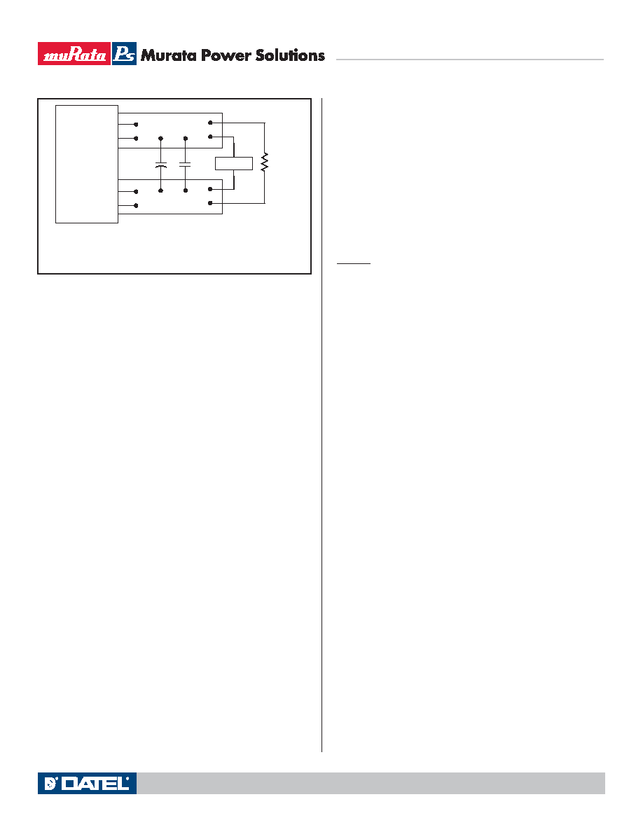
Figure 4. Measuring Output Ripple and Noise (PARD)
C1
C1 = 0.1μF CERAMIC
C2 = 10μF TANTALUM
LOAD 2-3 INCHES (51-76mm) FROM MODULE
C2
RLOAD
6
5
COPPER STRIP
SCOPE
+OUTPUT
+SENSE
9
8
-SENSE
-OUTPUT
相关PDF资料 |
PDF描述 |
|---|---|
| HPSTP-19-5000-01 | INTERCONNECTION DEVICE |
| HPT-136-01-SM-D-RA | 72 CONTACT(S), MALE, RIGHT ANGLE TWO PART BOARD CONNECTOR, SOLDER |
| HPT-153-01-L-D-RA | 106 CONTACT(S), MALE, RIGHT ANGLE TWO PART BOARD CONNECTOR, SOLDER |
| HPT-153-01-LM-D-RA | 106 CONTACT(S), MALE, RIGHT ANGLE TWO PART BOARD CONNECTOR, SOLDER |
| HPT-153-01-S-D-RA | 106 CONTACT(S), MALE, RIGHT ANGLE TWO PART BOARD CONNECTOR, SOLDER |
相关代理商/技术参数 |
参数描述 |
|---|---|
| HPH1-A | 制造商:ADAM-TECH 制造商全称:Adam Technologies, Inc. 功能描述:.050 PIN HEADERS .050 [1.27] CENTERLINE |
| HPH1A01SGA | 制造商:ADAM-TECH 制造商全称:Adam Technologies, Inc. 功能描述:.050 PIN HEADERS .050 [1.27] CENTERLINE |
| HPH1A01SGB | 制造商:ADAM-TECH 制造商全称:Adam Technologies, Inc. 功能描述:.050 PIN HEADERS .050 [1.27] CENTERLINE |
| HPH1A01TA | 制造商:ADAM-TECH 制造商全称:Adam Technologies, Inc. 功能描述:.050 PIN HEADERS .050 [1.27] CENTERLINE |
| HPH1A01TB | 制造商:ADAM-TECH 制造商全称:Adam Technologies, Inc. 功能描述:.050 PIN HEADERS .050 [1.27] CENTERLINE |
发布紧急采购,3分钟左右您将得到回复。