- 您现在的位置:买卖IC网 > PDF目录296194 > HPH-12/30-D48PBHL2-C (MURATA POWER SOLUTIONS INC) 1-OUTPUT 360 W DC-DC REG PWR SUPPLY MODULE PDF资料下载
参数资料
| 型号: | HPH-12/30-D48PBHL2-C |
| 厂商: | MURATA POWER SOLUTIONS INC |
| 元件分类: | 电源模块 |
| 英文描述: | 1-OUTPUT 360 W DC-DC REG PWR SUPPLY MODULE |
| 封装: | ROHS COMPLIANT, HALF BRICK PACKAGE-9 |
| 文件页数: | 2/13页 |
| 文件大小: | 662K |
| 代理商: | HPH-12/30-D48PBHL2-C |
HPH-12/30-D48 Series
Isolated, 12 VOUT, 30A, Half-Brick DC/DC Converters
www.murata-ps.com
email: sales@murata-ps.com
27 May 2011
MDC_HPH-12/30-D48.A02 Page 10 of 13
appropriate value. If the short-circuit condition persists, another shutdown
cycle will initiate. This on/off cycling is called “hiccup mode”. The hiccup
cycling reduces the average output current, thereby preventing excessive
internal temperatures. A short circuit can be tolerated indenitely.
Remote Sense Input
Sense inputs compensate for output voltage inaccuracy delivered at the load.
This is done by correcting voltage drops along the output wiring such as mod-
erate IR drops and the current carrying capacity of PC board etch. Sense inputs
also improve the stability of the converter and load system by optimizing the
control loop phase margin.
Note: The Sense input and power Vout lines are internally connected through
low value resistors to their respective polarities so that the converter can
operate without external connection to the Sense. Nevertheless, if the Sense
function is not used for remote regulation, the user should connect +Sense to
+Vout and –Sense to –Vout at the converter pins.
The remote Sense lines carry very little current. They are also capacitively
coupled to the output lines and therefore are in the feedback control loop to
regulate and stabilize the output. As such, they are not low impedance inputs
and must be treated with care in PC board layouts. Sense lines on the PCB
should run adjacent to DC signals, preferably Ground. In cables and discrete
wiring, use twisted pair, shielded tubing or similar techniques.
Please observe Sense inputs tolerance to avoid improper operation:
[Vout(+) –Vout(-)] – [ Sense(+) – Sense(-)] ≤ 10% of Vout
a single xed resistor connected between the Trim input and either the +Sense
or –Sense terminals. (On some converters, an external user-supplied precision
DC voltage may also be used for trimming). Trimming resistors should have a
low temperature coefcient (±100 ppm/deg.C or less) and be mounted close
to the converter. Keep leads short. If the trim function is not used, leave the
trim unconnected. With no trim, the converter will exhibit its specied output
voltage accuracy.
There are two CAUTION’s to be aware for the Trim input:
CAUTION: To avoid unplanned power down cycles, do not exceed EITHER the
maximum output voltage OR the maximum output power when setting the trim.
Be particularly careful with a trimpot. If the output voltage is excessive, the
OVP circuit may inadvertantly shut down the converter. If the maximum power
is exceeded, the converter may enter current limiting. If the power is exceeded
for an extended period, the converter may overheat and encounter overtem-
perature shut down.
CAUTION: Be careful of external electrical noise. The Trim input is a senstive
input to the converter’s feedback control loop. Excessive electrical noise may
cause instability or oscillation. Keep external connections short to the Trim
input. Use shielding if needed. Also consider adding a small value ceramic
capacitor between the Trim and –Vout to bypass RF and electrical noise.
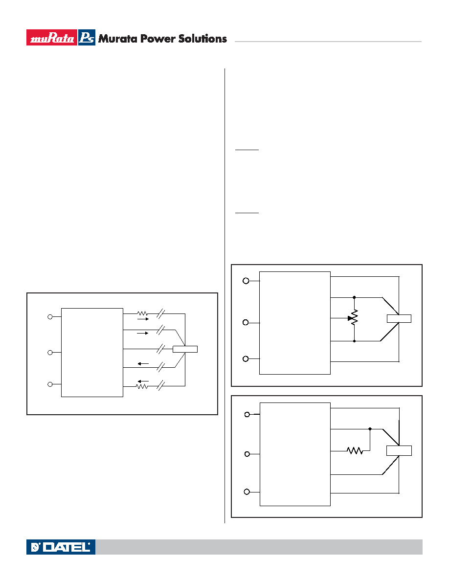
Figure 5. Remote Sense Circuit Conguration
Output overvoltage protection is monitored at the output voltage pin, not the
Sense pin. Therefore excessive voltage differences between Vout and Sense
together with trim adjustment of the output can cause the overvoltage protec-
tion circuit to activate and shut down the output.
Power derating of the converter is based on the combination of maximum
output current and the highest output voltage. Therefore the designer must insure:
(Vout at pins) x (Iout) ≤ (Max. rated output power)
Trimming the Output Voltage
The Trim input to the converter allows the user to adjust the output voltage
over the rated trim range (please refer to the Specications). In the trim equa-
tions and circuit diagrams that follow, trim adjustments use either a trimpot or
LOAD
5
8
7
6
9
Contact and PCB resistance
losses due to IR drops
Contact and PCB resistance
losses due to IR drops
+OUTPUT
+SENSE
TRIM
-SENSE
-OUTPUT
-INPUT
ON/OFF
CONTROL
+INPUT
1
3
4
Sense Current
I OUT
Sense Return
I OUT Return
Figure 6. Trim adjustments using a trimpot
LOAD
5
8
7
6
5-22
TURNS
1
3
4
9
+OUTPUT
+SENSE
TRIM
-SENSE
-OUTPUT
-INPUT
ON/OFF
CONTROL
+INPUT
Figure 7. Trim adjustments to Increase Output Voltage using a Fixed Resistor
LOAD
5
8
7
6
R TRIM UP
1
3
4
9
+OUTPUT
+SENSE
TRIM
-SENSE
-OUTPUT
-INPUT
ON/OFF
CONTROL
+INPUT
相关PDF资料 |
PDF描述 |
|---|---|
| HPSTP-19-5000-01 | INTERCONNECTION DEVICE |
| HPT-136-01-SM-D-RA | 72 CONTACT(S), MALE, RIGHT ANGLE TWO PART BOARD CONNECTOR, SOLDER |
| HPT-153-01-L-D-RA | 106 CONTACT(S), MALE, RIGHT ANGLE TWO PART BOARD CONNECTOR, SOLDER |
| HPT-153-01-LM-D-RA | 106 CONTACT(S), MALE, RIGHT ANGLE TWO PART BOARD CONNECTOR, SOLDER |
| HPT-153-01-S-D-RA | 106 CONTACT(S), MALE, RIGHT ANGLE TWO PART BOARD CONNECTOR, SOLDER |
相关代理商/技术参数 |
参数描述 |
|---|---|
| HPH1-A | 制造商:ADAM-TECH 制造商全称:Adam Technologies, Inc. 功能描述:.050 PIN HEADERS .050 [1.27] CENTERLINE |
| HPH1A01SGA | 制造商:ADAM-TECH 制造商全称:Adam Technologies, Inc. 功能描述:.050 PIN HEADERS .050 [1.27] CENTERLINE |
| HPH1A01SGB | 制造商:ADAM-TECH 制造商全称:Adam Technologies, Inc. 功能描述:.050 PIN HEADERS .050 [1.27] CENTERLINE |
| HPH1A01TA | 制造商:ADAM-TECH 制造商全称:Adam Technologies, Inc. 功能描述:.050 PIN HEADERS .050 [1.27] CENTERLINE |
| HPH1A01TB | 制造商:ADAM-TECH 制造商全称:Adam Technologies, Inc. 功能描述:.050 PIN HEADERS .050 [1.27] CENTERLINE |
发布紧急采购,3分钟左右您将得到回复。