- 您现在的位置:买卖IC网 > PDF目录175496 > HW004A0A1 1-OUTPUT DC-DC REG PWR SUPPLY MODULE PDF资料下载
参数资料
| 型号: | HW004A0A1 |
| 元件分类: | 电源模块 |
| 英文描述: | 1-OUTPUT DC-DC REG PWR SUPPLY MODULE |
| 文件页数: | 17/27页 |
| 文件大小: | 519K |
| 代理商: | HW004A0A1 |
第1页第2页第3页第4页第5页第6页第7页第8页第9页第10页第11页第12页第13页第14页第15页第16页当前第17页第18页第19页第20页第21页第22页第23页第24页第25页第26页第27页
HW/HC 4A – 6A Series Power Modules; dc-dc Converters
18 – 36 Vdc & 36 – 75 Vdc Input; 1.0Vdc to 5Vdc Output
Data Sheet
July 7, 2003
24
Tyco Electronics Power Systems
Surface Mount Information (cont)
The minimum recommended nozzle diameter for
reliable operation is 6mm. The maximum nozzle outer
diameter, which will safely fit within the allowable
component spacing, is 9 mm.
Oblong or oval nozzles up to 11 x 9 mm may also be
used within the space available.
For further information please contact your local Tyco
Electronics Power Systems Technical Sales
Representative.
Reflow Soldering Information
The HW005 family of power modules is available for
either Through-Hole (TH) or Surface Mount (SMT)
soldering. These power modules are large mass, low
thermal resistance devices and typically heat up
slower than other SMT components. It is
recommended that the customer review data sheets
in order to customize the solder reflow profile for each
application board assembly.
The following instructions must be observed when
SMT soldering these units. Failure to observe these
instructions may result in the failure of or cause
damage to the modules, and can adversely affect
long-term reliability.
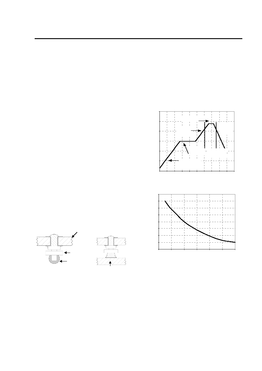
The surface mountable modules in the HW005 family
use our newest SMT technology called “Column Pin”
(CP) connectors. Fig 71 shows the new CP connector
before and after reflow soldering onto the end-board
assembly.
HW005 Board
Insulator
Solder Ball
End assembly PCB
Figure 71. Column Pin Connector Before and After
Reflow Soldering
The CP is constructed from a solid copper pin with an
integral solder ball attached, which is composed of
tin/lead (Sn/Pb) solder. The CP connector design is
able to compensate for large amounts of co-planarity
and still ensure a reliable SMT solder joint.
Typically, the eutectic solder melts at 183
oC, wets the
land, and subsequently wicks the device connection.
Sufficient time must be allowed to fuse the plating on
the connection to ensure a reliable solder joint. There
are several types of SMT reflow technologies
currently used in the industry. These surface mount
power modules can be reliably soldered using natural
forced convection, IR (radiant infrared), or a
combination of convection/IR. For reliable soldering
the solder reflow profile should be established by
accurately measuring the modules CP connector
temperatures.
R
E
FLOW
TEMP
(
°C)
0
50
100
150
200
250
300
Preheat zone
max 4oCs-1
Soak zone
30-240s
Heat zone
max 4oCs-1
Peak Temp 235oC
Cooling
zone
1-4oCs-1
T
lim above
205oC
REFLOW TIME (S)
Figure 72. Recommended Reflow Profile
MAX
TEMP
S
O
LD
ER
(
°C)
200
205
210
215
220
225
230
235
240
0
10
203040
5060
TIME LIMIT (S)
Figure 73. Time Limit Curve Above 205
oC Reflow
Lead Free Soldering
The HW005 family of power modules are designed to
be used in a conventional Tin/Lead (Sn/Pd) solder
process where peak reflow temperatures are limited
to less than 235
oC. Users who wish to assemble
these modules in a Lead Free solder process which, it
is expected, will require the use of higher peak reflow
temperatures should contact your local Tyco Power
Systems technical representative for more
information.
相关PDF资料 |
PDF描述 |
|---|---|
| HWB401SDX0 | 4M X 8 FLASH 12V PROM CARD, 250 ns, XMA68 |
| HWZT-1.79MD-A | CERAMIC RESONATOR, 1.79 MHz |
| HWZTFREQ2MD | CERAMIC RESONATOR, 12.51 MHz - 60 MHz |
| HWZT-FREQ2MD | CERAMIC RESONATOR, 12.51 MHz - 60 MHz |
| HWZT-2.00MHZMD-A | CERAMIC RESONATOR, 2 MHz |
相关代理商/技术参数 |
参数描述 |
|---|---|
| HW004A0A1-S | 功能描述:DC/DC转换器 SMT 4A, IN 48V OUT 5V RoHS:否 制造商:Murata 产品: 输出功率: 输入电压范围:3.6 V to 5.5 V 输入电压(标称): 输出端数量:1 输出电压(通道 1):3.3 V 输出电流(通道 1):600 mA 输出电压(通道 2): 输出电流(通道 2): 安装风格:SMD/SMT 封装 / 箱体尺寸: |
| HW004A0A1-SB | 制造商:LINEAGEPOWER 制造商全称:LINEAGEPOWER 功能描述:18-36Vdc & 36-75Vdc Input; 1.0V-5Vdc Output; 4A - 6A Output Current |
| HW004A0A1-SZ | 功能描述:DC/DC转换器 48Vin 5Vout 4A SMT RoHS:否 制造商:Murata 产品: 输出功率: 输入电压范围:3.6 V to 5.5 V 输入电压(标称): 输出端数量:1 输出电压(通道 1):3.3 V 输出电流(通道 1):600 mA 输出电压(通道 2): 输出电流(通道 2): 安装风格:SMD/SMT 封装 / 箱体尺寸: |
| HW004A0A1Z | 功能描述:DC/DC转换器 48Vin 5Vout 4A Th RoHS:否 制造商:Murata 产品: 输出功率: 输入电压范围:3.6 V to 5.5 V 输入电压(标称): 输出端数量:1 输出电压(通道 1):3.3 V 输出电流(通道 1):600 mA 输出电压(通道 2): 输出电流(通道 2): 安装风格:SMD/SMT 封装 / 箱体尺寸: |
| HW004A0A1-Z | 制造商:GE Critical Power 功能描述: |
发布紧急采购,3分钟左右您将得到回复。