- 您现在的位置:买卖IC网 > PDF目录175496 > HW004A0A1 1-OUTPUT DC-DC REG PWR SUPPLY MODULE PDF资料下载
参数资料
| 型号: | HW004A0A1 |
| 元件分类: | 电源模块 |
| 英文描述: | 1-OUTPUT DC-DC REG PWR SUPPLY MODULE |
| 文件页数: | 9/27页 |
| 文件大小: | 519K |
| 代理商: | HW004A0A1 |
第1页第2页第3页第4页第5页第6页第7页第8页当前第9页第10页第11页第12页第13页第14页第15页第16页第17页第18页第19页第20页第21页第22页第23页第24页第25页第26页第27页
Data Sheet
July 7, 2003
HW/HC 4A – 6A Series Power Modules; dc-dc Converters
18 – 36 Vdc & 36 – 75 Vdc Input; 1.0Vdc to 5Vdc Output
Tyco Electronics Power Systems
17
Feature Descriptions
Overcurrent Protection
To provide protection in a fault (output overload)
condition, the unit is equipped with internal
current-limiting circuitry and can endure current limiting
continuously. At the point of current-limit inception, the
unit enters hiccup mode. The unit operates normally
once the output current is brought back into its specified
range. The average output current during hiccup is 10%
IO, max.
Remote On/Off
Two remote on/off options are available. Positive logic
turns the module on during a logic high voltage on the
ON/OFF pin, and off during a logic low. Negative logic
remote On/Off, device code suffix “1”, turns the module
off during a logic high and on during a logic low.
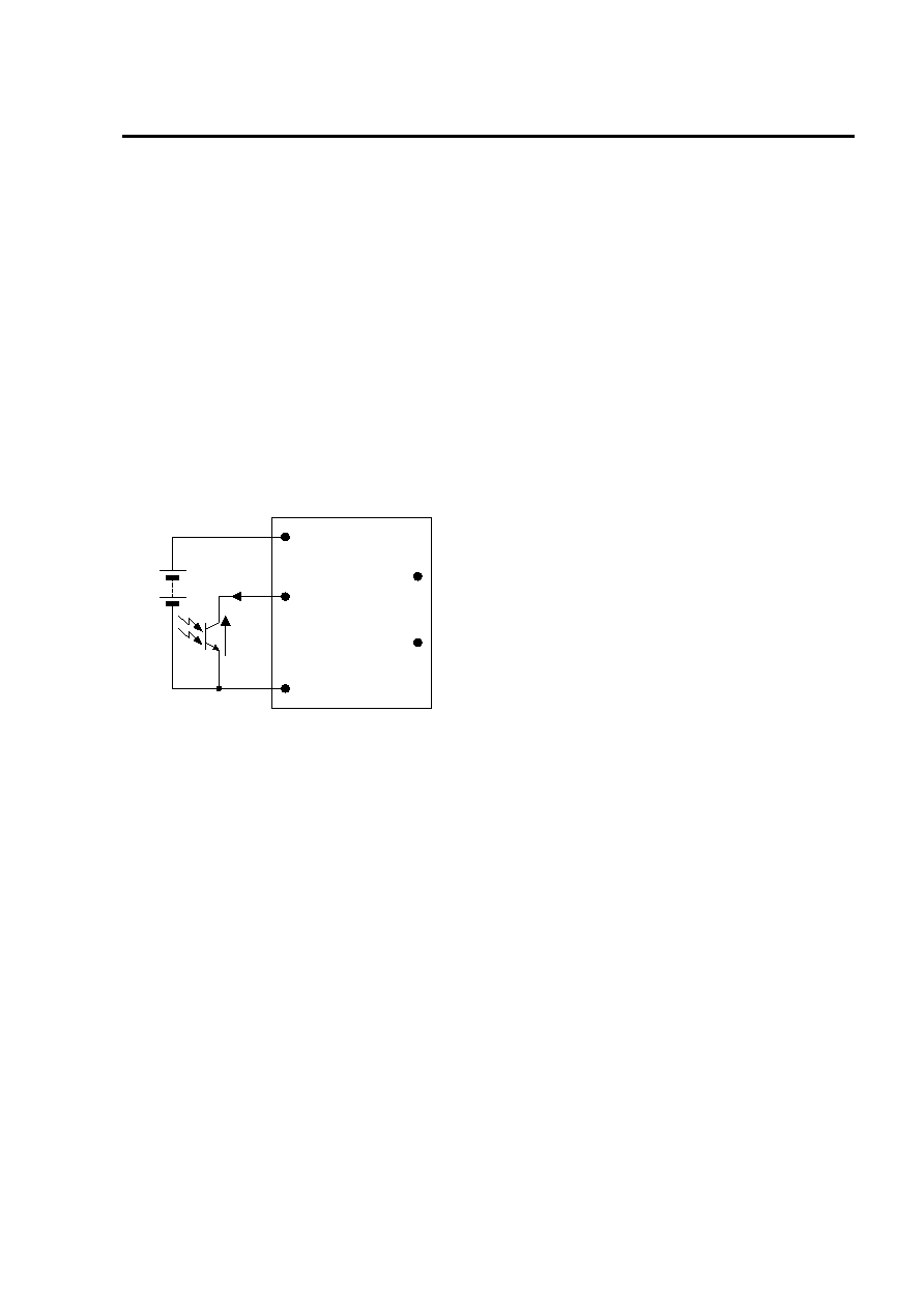
ON/OFF
VIN(+)
VIN(-)
Ion/off
Von/off
VO
COM
Figure 64. Remote On/Off Implementation
To turn the power module on and off, the user must
supply a switch (open collector or equivalent) to control
the voltage (Von/off) between the ON/OFF terminal and
the VIN(-) terminal. Logic low is 0V ≤ Von/off ≤ 1.2V. The
maximum Ion/off during a logic low is 1mA, the switch
should be maintain a logic low level whilst sinking this
current.
During a logic high, the typical Von/off generated by the
module is 5.8V, and the maximum allowable leakage
current at Von/off = 5.8V is 10A.
If not using the remote on/off feature:
For positive logic, leave the ON/OFF pin open.
For negative logic, short the ON/OFF pin to VIN(-).
Overtemperature Protection
To provide protection in a fault condition, the unit is
equipped with a thermal shutdown circuit. The unit will
shutdown if the overtemperature threshold of 125
oC is
exceeded at the thermal reference point Tref . Once the
unit goes into thermal shutdown it will then wait to cool
before attempting to restart.
Input Undervoltage Lockout
At input voltages below the input undervoltage lockout
limit, the module operation is disabled. The module will
begin to operate at an input voltage above the
undervoltage lockout turn-on threshold.
Output Overvoltage Protection
The output overvoltage protection consists of circuitry
that internally clamps the output voltage. If a more
accurate output overvoltage protection scheme is
required then this should be implemented externally via
use of the remote on/off pin.
相关PDF资料 |
PDF描述 |
|---|---|
| HWB401SDX0 | 4M X 8 FLASH 12V PROM CARD, 250 ns, XMA68 |
| HWZT-1.79MD-A | CERAMIC RESONATOR, 1.79 MHz |
| HWZTFREQ2MD | CERAMIC RESONATOR, 12.51 MHz - 60 MHz |
| HWZT-FREQ2MD | CERAMIC RESONATOR, 12.51 MHz - 60 MHz |
| HWZT-2.00MHZMD-A | CERAMIC RESONATOR, 2 MHz |
相关代理商/技术参数 |
参数描述 |
|---|---|
| HW004A0A1-S | 功能描述:DC/DC转换器 SMT 4A, IN 48V OUT 5V RoHS:否 制造商:Murata 产品: 输出功率: 输入电压范围:3.6 V to 5.5 V 输入电压(标称): 输出端数量:1 输出电压(通道 1):3.3 V 输出电流(通道 1):600 mA 输出电压(通道 2): 输出电流(通道 2): 安装风格:SMD/SMT 封装 / 箱体尺寸: |
| HW004A0A1-SB | 制造商:LINEAGEPOWER 制造商全称:LINEAGEPOWER 功能描述:18-36Vdc & 36-75Vdc Input; 1.0V-5Vdc Output; 4A - 6A Output Current |
| HW004A0A1-SZ | 功能描述:DC/DC转换器 48Vin 5Vout 4A SMT RoHS:否 制造商:Murata 产品: 输出功率: 输入电压范围:3.6 V to 5.5 V 输入电压(标称): 输出端数量:1 输出电压(通道 1):3.3 V 输出电流(通道 1):600 mA 输出电压(通道 2): 输出电流(通道 2): 安装风格:SMD/SMT 封装 / 箱体尺寸: |
| HW004A0A1Z | 功能描述:DC/DC转换器 48Vin 5Vout 4A Th RoHS:否 制造商:Murata 产品: 输出功率: 输入电压范围:3.6 V to 5.5 V 输入电压(标称): 输出端数量:1 输出电压(通道 1):3.3 V 输出电流(通道 1):600 mA 输出电压(通道 2): 输出电流(通道 2): 安装风格:SMD/SMT 封装 / 箱体尺寸: |
| HW004A0A1-Z | 制造商:GE Critical Power 功能描述: |
发布紧急采购,3分钟左右您将得到回复。