- 您现在的位置:买卖IC网 > PDF目录20100 > ICL7107SCPL (Intersil)IC ADC 3.5 DIGIT LED 40-DIP PDF资料下载
参数资料
| 型号: | ICL7107SCPL |
| 厂商: | Intersil |
| 文件页数: | 10/16页 |
| 文件大小: | 0K |
| 描述: | IC ADC 3.5 DIGIT LED 40-DIP |
| 标准包装: | 9 |
| 显示器类型: | LED |
| 配置: | 7 段显示 |
| 数字或字符: | A/D,3.5 位数字 |
| 电源电压: | 4.75 V ~ 5.25 V |
| 工作温度: | 0°C ~ 70°C |
| 安装类型: | 通孔 |
| 封装/外壳: | 40-DIP(0.600",15.24mm) |
| 供应商设备封装: | 40-DIP |
| 包装: | 管件 |
�� �
�
�ICL7106,� ICL7107,� ICL7107S�
�Component� Value� Selection�
�Integrating� Resistor�
�Both� the� buffer� amplifier� and� the� integrator� have� a� class� A�
�output� stage� with� 100� μ� A� of� quiescent� current.� They� can�
�supply� 4� μ� A� of� drive� current� with� negligible� nonlinearity.� The�
�integrating� resistor� should� be� large� enough� to� remain� in� this�
�very� linear� region� over� the� input� voltage� range,� but� small�
�enough� that� undue� leakage� requirements� are� not� placed� on�
�the� PC� board.� For� 2V� full� scale,� 470k� ?� is� near� optimum� and�
�similarly� a� 47k� ?� for� a� 200mV� scale.�
�Integrating� Capacitor�
�The� integrating� capacitor� should� be� selected� to� give� the�
�maximum� voltage� swing� that� ensures� tolerance� buildup� will�
�not� saturate� the� integrator� swing� (approximately.� 0.3V� from�
�either� supply).� In� the� ICL7106� or� the� ICL7107,� when� the�
�analog� COMMON� is� used� as� a� reference,� a� nominal� +2V� full-�
�scale� integrator� swing� is� fine.� For� the� ICL7107� with� +5V�
�supplies� and� analog� COMMON� tied� to� supply� ground,� a�
�±� 3.5V� to� +4V� swing� is� nominal.� For� three� readings/second�
�(48kHz� clock)� nominal� values� for� C� lNT� are� 0.22� μ� F� and�
�0.10� μ� F,� respectively.� Of� course,� if� different� oscillator�
�frequencies� are� used,� these� values� should� be� changed� in�
�inverse� proportion� to� maintain� the� same� output� swing.�
�An� additional� requirement� of� the� integrating� capacitor� is� that�
�it� must� have� a� low� dielectric� absorption� to� prevent� roll-over�
�errors.� While� other� types� of� capacitors� are� adequate� for� this�
�application,� polypropylene� capacitors� give� undetectable�
�errors� at� reasonable� cost.�
�Auto-Zero� Capacitor�
�The� size� of� the� auto-zero� capacitor� has� some� influence� on�
�the� noise� of� the� system.� For� 200mV� full� scale� where� noise� is�
�very� important,� a� 0.47� μ� F� capacitor� is� recommended.� On� the�
�2V� scale,� a� 0.047� μ� F� capacitor� increases� the� speed� of�
�recovery� from� overload� and� is� adequate� for� noise� on� this�
�scale.�
�Reference� Capacitor�
�A� 0.1� μ� F� capacitor� gives� good� results� in� most� applications.�
�However,� where� a� large� common� mode� voltage� exists� (i.e.,�
�the� REF� LO� pin� is� not� at� analog� COMMON)� and� a� 200mV�
�scale� is� used,� a� larger� value� is� required� to� prevent� roll-over�
�Reference� Voltage�
�The� analog� input� required� to� generate� full� scale� output� (2000�
�counts)� is:� V� lN� =� 2V� REF� .� Thus,� for� the� 200mV� and� 2V� scale,�
�V� REF� should� equal� 100mV� and� 1V,� respectively.� However,� in�
�many� applications� where� the� A/D� is� connected� to� a�
�transducer,� there� will� exist� a� scale� factor� other� than� unity�
�between� the� input� voltage� and� the� digital� reading.� For�
�instance,� in� a� weighing� system,� the� designer� might� like� to�
�have� a� full� scale� reading� when� the� voltage� from� the�
�transducer� is� 0.662V.� Instead� of� dividing� the� input� down� to�
�200mV,� the� designer� should� use� the� input� voltage� directly�
�and� select� V� REF� =� 0.341V.� Suitable� values� for� integrating�
�resistor� and� capacitor� would� be� 120k� ?� and� 0.22� μ� F.� This�
�makes� the� system� slightly� quieter� and� also� avoids� a� divider�
�network� on� the� input.� The� ICL7107� with� ±� 5V� supplies� can�
�accept� input� signals� up� to� ±� 4V.� Another� advantage� of� this�
�system� occurs� when� a� digital� reading� of� zero� is� desired� for�
�V� IN� ≠� 0.� Temperature� and� weighing� systems� with� a� variable�
�fare� are� examples.� This� offset� reading� can� be� conveniently�
�generated� by� connecting� the� voltage� transducer� between� IN�
�HI� and� COMMON� and� the� variable� (or� fixed)� offset� voltage�
�between� COMMON� and� IN� LO.�
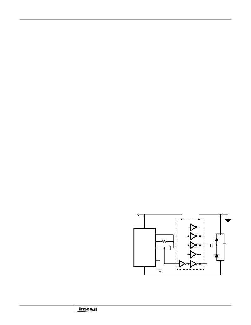
�ICL7107� Power� Supplies�
�The� ICL7107� is� designed� to� work� from� ±� 5V� supplies.�
�However,� if� a� negative� supply� is� not� available,� it� can� be�
�generated� from� the� clock� output� with� 2� diodes,� 2� capacitors,�
�and� an� inexpensive� lC.� Figure� 10� shows� this� application.� See�
�ICL7660� data� sheet� for� an� alternative.�
�In� fact,� in� selected� applications� no� negative� supply� is�
�required.� The� conditions� to� use� a� single� +5V� supply� are:�
�1.� The� input� signal� can� be� referenced� to� the� center� of� the�
�common� mode� range� of� the� converter.�
�2.� The� signal� is� less� than� ±� 1.5V.�
�3.� An� external� reference� is� used.�
�V+�
�CD4009�
�V+�
�OSC� 1�
�f� =� -----------� For� 48kHz� Clock� (3� Readings/sec),�
�error.� Generally� 1� μ� F� will� hold� the� roll-over� error� to� 0.5� count�
�in� this� instance.�
�Oscillator� Components�
�For� all� ranges� of� frequency� a� 100k� ?� resistor� is� recommended�
�and� the� capacitor� is� selected� from� the� equation:�
�0.45�
�RC�
�OSC� 2�
�OSC� 3�
�ICL7107�
�GND�
�V-�
�V-� =� 3.3V�
�1N914�
�0.047�
�μ� F�
�1N914�
�+�
�10�
�μ� F�
�-�
�C� =� 100pF.�
�FIGURE� 10.� GENERATING� NEGATIVE� SUPPLY� FROM� +5V�
�10�
�FN3082.8�
�相关PDF资料 |
PDF描述 |
|---|---|
| EMM43DRSI | CONN EDGECARD 86POS DIP .156 SLD |
| RBB13DHHN | CONN EDGE DUAL .050 DIP 26 POS |
| ICL7107CM44 | IC ADC 3.5 DIGIT LED 44-MQFP |
| VI-2NY-CV-F1 | CONVERTER MOD DC/DC 3.3V 99W |
| JMK212BJ335MG-T | CAP CER 3.3UF 6.3V 20% X5R 0805 |
相关代理商/技术参数 |
参数描述 |
|---|---|
| ICL7107SCPLZ | 功能描述:LED显示驱动器 ADC 3 5 DIG LED DRVR COM RoHS:否 制造商:Micrel 数位数量:5 片段数量: 安装风格:SMD/SMT 封装 / 箱体:PLCC-44 工作电源电压:4.75 V to 11 V 最大电源电流:10 mA 最大工作温度:+ 85 C 最小工作温度:- 40 C 封装:Tube |
| ICL7109 | 制造商:INTERSIL 制造商全称:Intersil Corporation 功能描述:N-CHANNEL JFET |
| ICL7109 WAF | 制造商:Harris Corporation 功能描述: |
| ICL71091DL | 制造商:Harris Corporation 功能描述: |
| ICL7109C/D | 功能描述:显示驱动器和控制器 RoHS:否 制造商:Panasonic Electronic Components 工作电源电压:2.7 V to 5.5 V 最大工作温度: 安装风格:SMD/SMT 封装 / 箱体:QFN-44 封装:Reel |
发布紧急采购,3分钟左右您将得到回复。