- 您现在的位置:买卖IC网 > Datasheet目录690 > ICM7216DIPI (Intersil)IC COUNTER/TIMER FREQ 8DIG 28DIP Datasheet资料下载
参数资料
| 型号: | ICM7216DIPI |
| 厂商: | Intersil |
| 文件页数: | 11/18页 |
| 文件大小: | 0K |
| 描述: | IC COUNTER/TIMER FREQ 8DIG 28DIP |
| 标准包装: | 78 |
| 系列: | * |
| 其它名称: | 7216DIPI NT5007 |
�� �
�
�ICM7216B,� ICM7216D�
�INPUT� and� OUTPUT� pins� each� contribute� about� 5pF� to� CIN�
�SIGNAL� A�
�and� COUT� .� For� maximum� stability� of� frequency,� CIN� and�
�SIGNAL� B�
�2�
�2�
�INPUT� A�
�INPUT� B�
�COUT� should� be� approximately� twice� the� specified� crystal�
�static� capacitance.�
�In� cases� where� non� decade� prescalers� are� used� it� may� be�
�V� DD�
�V� DD�
�desirable� to� use� a� crystal� which� is� neither� 10MHz� or� 1MHz.�
�In� that� case� both� the� multiplex� rate� and� time� between�
�N.O.�
�PRIME�
�150K�
�measurements� will� be� different.� The� multiplex� rate� is�
�f� MUX� =� -------------------� for� 10MHz� mode� and� f� MUX� =� -------------------� for�
�2� � 10�
�2� � 10�
�1�
�100K�
�1N914�
�1�
�0.1� μ� F�
�1�
�10K�
�1�
�10nF�
�f� OSC� f� OSC�
�4� 3�
�the� 1MHz� mode.� The� time� between� measurements� is�
�� 10�
�2� � 10�
�V� SS�
�DEVICE�
�V� SS�
�TYPE�
�V� SS�
�6�
�2� -------------------�
�f� OSC�
�5�
�in� the� 10MHz� mode� and� -------------------� in� the� 1MHz� mode.�
�f� OSC�
�1�
�2�
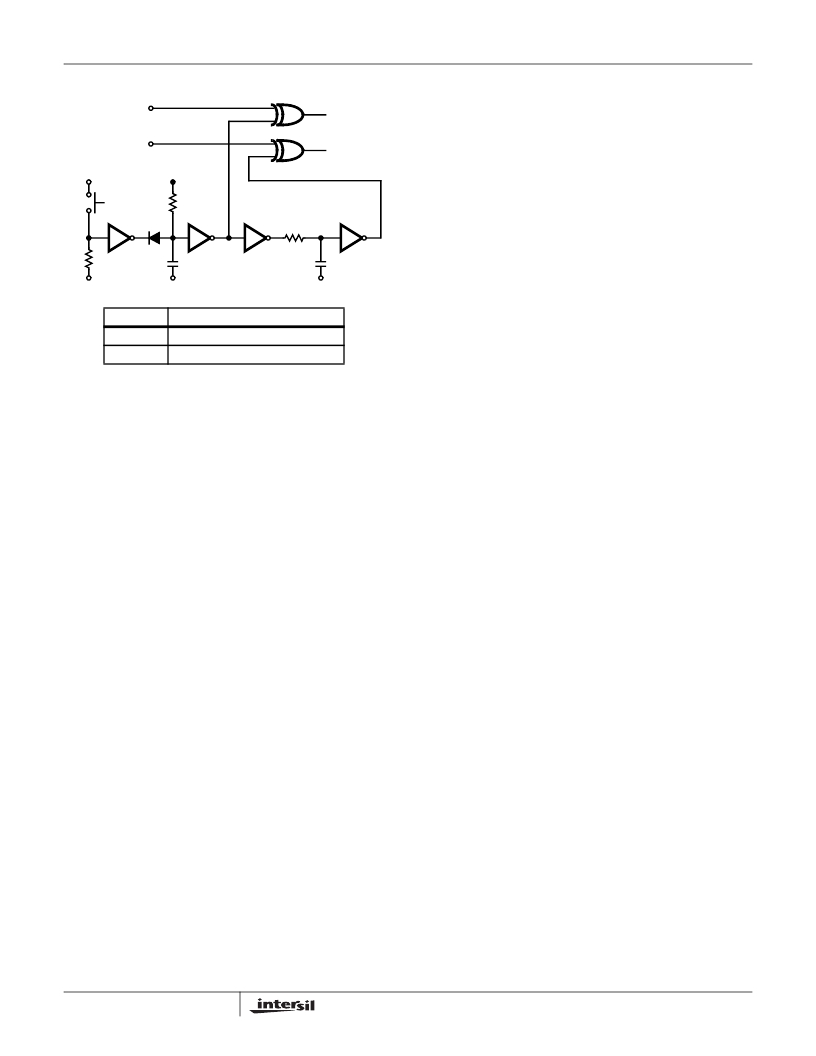
�CD4049B� Inverting� Buffer�
�CD4070B� Exclusive� -� OR�
�The� crystal� and� oscillator� components� should� be� located� as�
�close� to� the� chip� as� practical� to� minimize� pickup� from� other�
�signals.� Coupling� from� the� EXTERNAL� OSClLLATOR�
�g� M� =� ω� C� IN� C� OUT� R� S� ?� 1� +� --------� ?�
�where� C� L� =� ?� ---------------------------------� ?�
�oscillator� temperature� coefficient� of� 20� PPM� will� cause� a�
�measurement� error� of� 20� PPM�
�-------------------�
�FIGURE� 10.� PRIMING� CIRCUIT,� SIGNALS� A� AND� B� BOTH�
�HIGH� OR� LOW�
�Following� the� priming� procedure� (when� in� single� event� or� 1�
�cycle� range)� the� device� is� ready� to� measure� one� (only)�
�event.�
�When� timing� repetitive� signals,� it� is� not� necessary� to� “prime”�
�the� lCM7216B� as� the� first� alternating� signal� states�
�automatically� prime� the� device.� See� Figure� 1.�
�During� any� time� interval� measurement� cycle,� the� lCM7216B�
�require� 200ms� following� B� going� low� to� update� all� internal�
�logic.� A� new� measurement� cycle� will� not� take� place� until�
�completion� of� this� internal� update� time.�
�Oscillator� Considerations�
�The� oscillator� is� a� high� gain� CMOS� inverter.� An� external�
�resistor� of� 10M� ?� to� 22M� ?� should� be� connected� between� the�
�OSCillator� INPUT� and� OUTPUT� to� provide� biasing.� The�
�oscillator� is� designed� to� work� with� a� parallel� resonant� 10MHz�
�quartz� crystal� with� a� static� capacitance� of� 22pF� and� a� series�
�resistance� of� less� than� 35� ?� .�
�For� a� specific� crystal� and� load� capacitance,� the� required� gM�
�can� be� calculated� as� follows:�
�2� ?� C� O� ?� 2�
�?� C� L� ?�
�?� C� IN� C� OUT� ?�
�?� C� IN� +� C� OUT� ?�
�CO� =� Crystal� Static� Capacitance�
�RS� =� Crystal� Series� Resistance�
�CIN� =� Input� Capacitance�
�COUT� =� Output� Capacitance�
�ω� =� 2� π� f�
�The� required� gM� should� not� exceed� 50%� of� the� gM� specified�
�for� the� lCM7216� to� insure� reliable� startup.� The� OSCillator�
�11�
�INPUT� to� the� OSClLLATOR� OUTPUT� or� INPUT� can� cause�
�undesirable� shifts� in� oscillator� frequency.�
�Display� Considerations�
�The� display� is� multiplexed� at� a� 500Hz� rate� with� a� digit� time� of�
�244� μ� s.� An� interdigit� blanking� time� of� 6� μ� s� is� used� to� prevent�
�display� ghosting� (faint� display� of� data� from� previous� digit�
�superimposed� on� the� next� digit).� Leading� zero� blanking� is�
�provided,� which� blanks� the� left� hand� zeroes� after� decimal�
�point� or� any� non� zero� digits.� Digits� to� the� right� of� the� decimal�
�point� are� always� displayed.� The� leading� zero� blanking� will� be�
�disabled� when� the� Main� Counter� overflows.�
�The� lCM7216B� and� lCM7216D� are� designed� to� drive�
�common� cathode� displays� at� peak� current� of� 15mA/segment�
�using� displays� with� VF� =� 1.8V� at� 15mA.� Resistors� can� be�
�added� in� series� with� the� segment� drivers� to� limit� the� display�
�current� in� very� efficient� displays,� if� required.� The� Typical�
�Performance� Curves� show� the� digit� and� segment� currents� as�
�a� function� of� output� voltage.�
�To� get� additional� brightness� out� of� the� displays,� VDD� may� be�
�increased� up� to� 6.0V.� However,� care� should� be� taken� to� see�
�that� maximum� power� and� current� ratings� are� not� exceeded.�
�The� segment� and� digit� outputs� in� lCM7216s� are� not� directly�
�compatible� with� either� TTL� or� CMOS� logic� when� driving�
�LEDs.� Therefore,� level� shifting� with� discrete� transistors� may�
�be� required� to� use� these� outputs� as� logic� signals.�
�Accuracy�
�In� a� Universal� Counter� crystal� drift� and� quantization� effects�
�cause� errors.� In� frequency,� period� and� time� interval�
�modes,� a� signal� derived� from� the� oscillator� is� used� in� either�
�the� Reference� Counter� or� Main� Counter.� Therefore,� in�
�these� modes� an� error� in� the� oscillator� frequency� will� cause�
�an� identical� error� in� the� measurement.� For� instance,� an�
�-------------------�
�o�
�C�
�o�
�C�
�相关PDF资料 |
PDF描述 |
|---|---|
| IKH1003000 | SWITCH DIP 1/2 PITCH |
| IKN0203000 | DIP SWITCH |
| IN421WB-E | FLASHLIGHT SWIVEL HEAD W/4AA |
| INL2AAE | FLASHLIGHT MID-RANGE IND 2AA LED |
| INL2DE | FLASHLIGHT MID-RANGE IND 2D LED |
相关代理商/技术参数 |
参数描述 |
|---|---|
| ICM7216DIPI WAF | 制造商:Intersil Corporation 功能描述: |
| ICM7216DLPL | 制造商:INTERSIL 制造商全称:Intersil Corporation 功能描述:8-Digit, Multi-Function, Frequency Counters/Timers |
| ICM7217 | 制造商:MAXIM 制造商全称:Maxim Integrated Products 功能描述:4 Digit (LED) Presettable Up/Down Counter |
| ICM7217_01 | 制造商:INTERSIL 制造商全称:Intersil Corporation 功能描述:4-Digit LED Display, Programmable Up/Down Counter |
| ICM7217A | 制造商:未知厂家 制造商全称:未知厂家 功能描述:Analog IC |
发布紧急采购,3分钟左右您将得到回复。