- 您现在的位置:买卖IC网 > PDF目录67114 > IDT54FCT543ALB8 (INTEGRATED DEVICE TECHNOLOGY INC) FCT SERIES, 8-BIT REGISTERED TRANSCEIVER, TRUE OUTPUT, CQCC28 PDF资料下载
参数资料
| 型号: | IDT54FCT543ALB8 |
| 厂商: | INTEGRATED DEVICE TECHNOLOGY INC |
| 元件分类: | 总线收发器 |
| 英文描述: | FCT SERIES, 8-BIT REGISTERED TRANSCEIVER, TRUE OUTPUT, CQCC28 |
| 封装: | LCC-28 |
| 文件页数: | 3/7页 |
| 文件大小: | 90K |
| 代理商: | IDT54FCT543ALB8 |
MILITARYANDCOMMERCIAL TEMPERATURERANGES
IDT54/74FCT543/A/C
FASTCMOSOCTALLATCHEDTRANSCEIVER
3
Symbol
Parameter
Test Conditions(1)
Min.
Typ.(2)
Max.
Unit
VIH
Input HIGH Level
Guaranteed Logic HIGH Level
2
—
V
VIL
Input LOW Level
Guaranteed Logic LOW Level
—
0.8
V
IIH
Input HIGH Current
VI = VCC
——
5
VCC = Max.
VI = 2.7V
—
5(4)
A
IIL
Input LOW Current
VI = 0.5V
—
–5(4)
VI = GND
—
–5
IOZH
VO = VCC
——
10
Off State (High Impedance)
VCC = Max.
VO = 2.7V
—
10(4)
A
IOZL
Output Current
VO = 0.5V
—
–10(4)
VO = GND
—
–10
VIK
Clamp Diode Voltage
VCC = Min., IIN = –18mA
—
–0.7
–1.2
V
IOS
Short Circuit Current
VCC = Max., VO = GND(3)
–60
–120
—
mA
VOH
Output HIGH Voltage
VCC = 3V, VIN = VLC or VHC, IOH = –32
μAVHC
VCC
—
VCC = Min
IOH = –300
μAVHC
VCC
—V
VIN = VIH or VIL
IOH = –12mA MIL
2.4
4.3
—
IOH = –15mA COM'L
2.4
4.3
—
VOL
Output LOW Voltage
VCC = 3V, VIN = VLC or VHC, IOL = 300
μA
—
GND
VLC
VCC = Min
IOL = 300
μA
—
GND
VLC(4)
V
VIN = VIH or VIL
IOL = 48mA MIL
—
0.3
0.55
IOL = 64mA COM'L
—
0.3
0.55
DC ELECTRICAL CHARACTERISTICS OVER OPERATING RANGE
Following Conditions Apply Unless Otherwise Specified: VLC = 0.2V; VHC = VCC - 0.2V
Commercial: TA = 0°C to +70°C, VCC = 5.0V ±5%, Military: TA = -55°C to +125°C, VCC = 5.0V ±10%
NOTES:
1. For conditions shown as Min. or Max., use appropriate value specified under Electrical Characteristics for the applicable device type.
2. Typical values are at VCC = 5.0V, +25°C ambient and maximum loading.
3. Not more than one output should be tested at one time. Duration of the test should not exceed one second.
4. This parameter is guaranteed but not ttested.
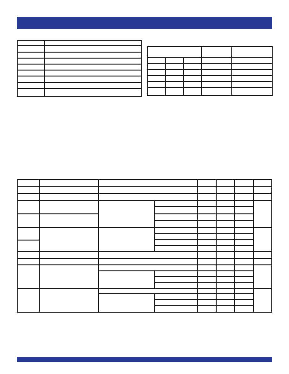
FUNCTION TABLE(1,2)
For A-to-B (Symmetric with B-to-A)
Latch
Output
Inputs
Status
Buffers
CEAB
LEAB
OEAB
A-to-B
B0–B7
H
X
Storing
High Z
X
H
X
Storing
X
H
X
High Z
L
Transparent
Current A Inputs
L
H
L
Storing
Previous* A Inputs
NOTES:
1. * Before
LEAB LOW-to-HIGH Transition
H = HIGH Voltage Level
L = LOW Voltage Level
X = Don’t Care
2. A-to-B data flow shown; B-to-A flow control is the same, except using
CEBA, LEBA
and
OEBA.
PIN DESCRIPTION
Pin Names
Description
OEAB
A-to-B Output Enable Input (Active LOW)
OEBA
B-to-A Output Enable Input (Active LOW)
CEAB
A-to-B Enable Input (Active LOW)
CEBA
B-to-A Enable Input (Active LOW)
LEAB
A-to-B Latch Enable Input (Active LOW)
LEBA
B-to-A Latch Enable Input (Active LOW)
A0–A7
A-to-B Data Inputs or B-to-A 3-State Outputs
B0–B7
B-to-A Data Inputs or A-to-B 3-State Outputs
相关PDF资料 |
PDF描述 |
|---|---|
| IDT54FCT574TEB | FCT SERIES, 8-BIT DRIVER, TRUE OUTPUT, CDFP20 |
| IDT54FCT648ATLB8 | FCT SERIES, 8-BIT REGISTERED TRANSCEIVER, INVERTED OUTPUT, CQCC28 |
| IDT54FCT652ATLB8 | FCT SERIES, 8-BIT REGISTERED TRANSCEIVER, TRUE OUTPUT, CQCC28 |
| IDT54FCT821BLB8 | FCT SERIES, 10-BIT DRIVER, TRUE OUTPUT, CQCC28 |
| IDT5991A-2JG8 | 5991 SERIES, PLL BASED CLOCK DRIVER, 8 TRUE OUTPUT(S), 0 INVERTED OUTPUT(S), PQCC32 |
相关代理商/技术参数 |
参数描述 |
|---|---|
| IDT54FCT543ATDB | 制造商:MAJOR 功能描述: |
| IDT54FCT573ADB | 制造商:Integrated Device Technology Inc 功能描述: |
| IDT54FCT573ATDB | 制造商:Integrated Device Technology Inc 功能描述: 制造商:Integrated Device Technology Inc 功能描述:IC REGISTER OCTAL D 20CERDIP |
| IDT54FCT573ATLB | 制造商:Integrated Device Technology Inc 功能描述:IC REGISTER OCTAL D 20LCC |
| IDT54FCT573CTDB | 制造商:Integrated Device Technology Inc 功能描述:IC REGISTER OCTAL D 20CERDIP |
发布紧急采购,3分钟左右您将得到回复。