- 您现在的位置:买卖IC网 > PDF目录11796 > IDTSSTUB32866BHLF (IDT, Integrated Device Technology Inc)IC BUFFER 25BIT CONF REG 96LFBGA PDF资料下载
参数资料
| 型号: | IDTSSTUB32866BHLF |
| 厂商: | IDT, Integrated Device Technology Inc |
| 文件页数: | 22/28页 |
| 文件大小: | 0K |
| 描述: | IC BUFFER 25BIT CONF REG 96LFBGA |
| 标准包装: | 270 |
| 应用: | DDR2 RDIMM |
| 接口: | 差分 |
| 电源电压: | 1.7 V ~ 1.9 V |
| 封装/外壳: | 96-LFBGA |
| 供应商设备封装: | 96-CABGA(13.5x5.5) |
| 包装: | 托盘 |
| 安装类型: | 表面贴装 |
| 产品目录页面: | 1254 (CN2011-ZH PDF) |
| 其它名称: | 800-1779 SSTUB32866BHLF |
第1页第2页第3页第4页第5页第6页第7页第8页第9页第10页第11页第12页第13页第14页第15页第16页第17页第18页第19页第20页第21页当前第22页第23页第24页第25页第26页第27页第28页
3
ICSSSTUB32866B
Advance Information
1165A—3/21/07
General Description
This 25-bit 1:1 or 14-bit 1:2 configurable registered buffer is designed for 1.7-V to 1.9-V VDD operation.
All clock and data inputs are compatible with the JEDEC standard for SSTL_18. The control inputs are LVCMOS. All
outputs are 1.8-V CMOS drivers that have been optimized to drive the DDR-II DIMM load. ICSSSTUB32866B operates
from a differential clock (CK and CK). Data are registered at the crossing of CK going high, and CK going low.
The C0 input controls the pinout configuration of the 1:2 pinout from A configuration (when low) to B configuration (when
high). The C1 input controls the pinout configuration from 25-bit 1:1 (when low) to 14-bit 1:2 (when high).
A - Pair Configuration (CO1 = 0, CI1 = 1 and CO2 = 0, CI2 = 1)
Parity that arrives one cycle after the data input to which it applies is checked on the PAR_IN of the first register.
The second register produces to PPO and QERR signals. The QERR of the first register is left floating. The valid
error information is latched on the QERR output of the second register. If an error occurs QERR is latched low for
two cycles or until Reset is low.
B - Single Configuration (CO = 0, C1 = 0)
The device supports low-power standby operation. When the reset input (RST) is low, the differential input receivers
are disabled, and undriven (floating) data, clock and reference voltage (VREF) inputs are allowed. In addition, when
RST is low all registers are reset, and all outputs are forced low. The LVCMOS RST and Cn inputs must always be
held at a valid logic high or low level. To ensure defined outputs from the register before a stable clock has been supplied,
RST must be held in the low state during power up.
In the DDR-II RDIMM application, RST is specified to be completely asynchronous with respect to CK and CK.
Therefore, no timing relationship can be guaranteed between the two. When entering reset, the register will be cleared
and the outputs will be driven low quickly, relative to the time to disable the differential input receivers. However, when
coming out of reset, the register will become active quickly, relative to the time to enable the differential input receivers.
As long as the data inputs are low, and the clock is stable during the time from the low-to-high transition of RST until
the input receivers are fully enabled, the design of the ICSSSTUB32866B must ensure that the outputs will remain
low, thus ensuring no glitches on the output.
The device monitors both DCS and CSR inputs and will gate the Qn outputs from changing states when both DCS and
CSR inputs are high. If either DCS or CSR input is low, the Qn outputs will function normally. The RST input has priority
over the DCS and CSR control and will force the outputs low. If the DCS-control functionality is not desired, then the
CSR input can be hardwired to ground, in which case, the setup-time requirement for DCS would be the same as for
the other D data inputs. Package options include 96-ball LFBGA (MO-205CC).
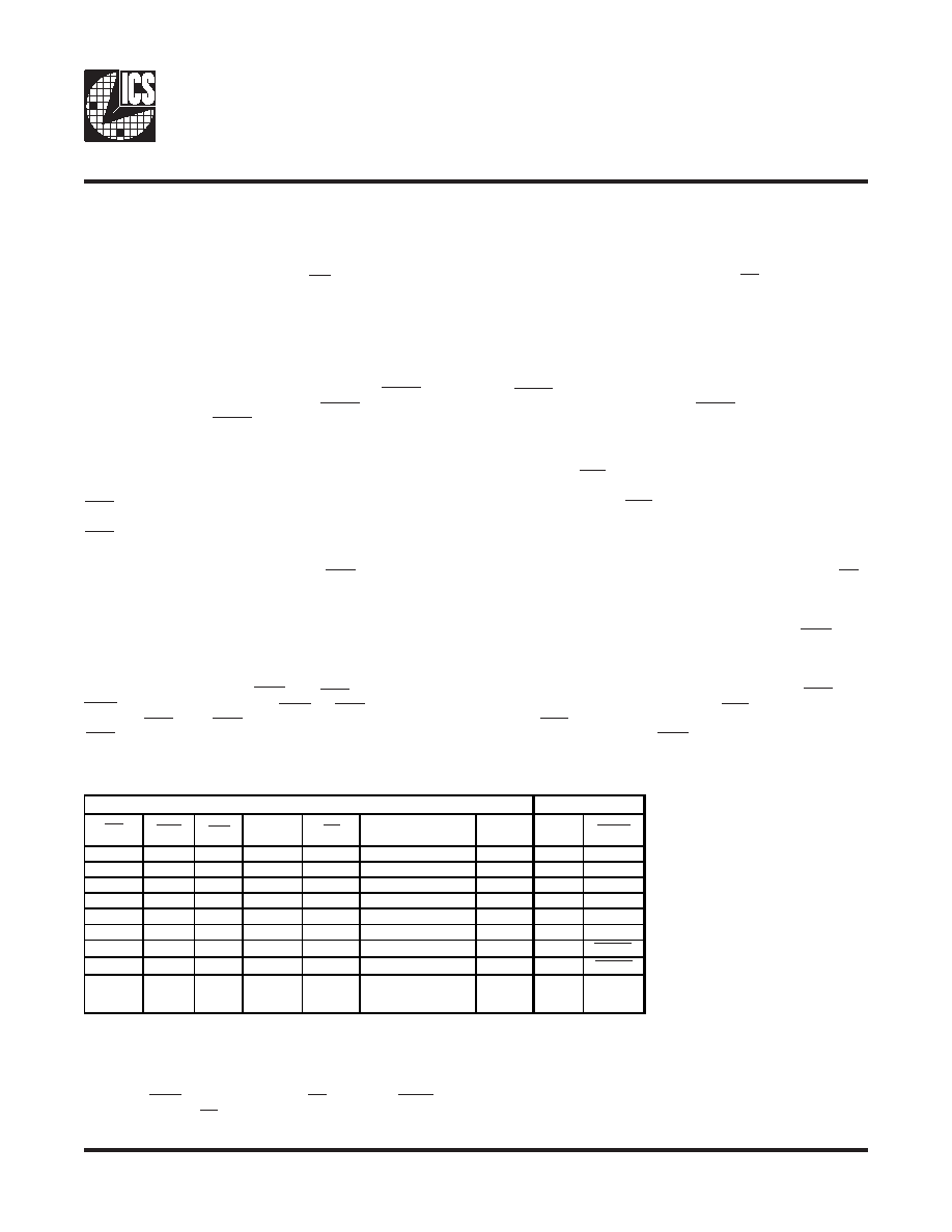
Parity and Standby Functionality Truth Table
Rst
DCS
CSR
CK
Sum of Inputs = H
(D1 - D25)
PAR_IN
PPO
QERR
HL
X
↑↓
Even
LLH
HL
X
↑↓
Odd
L
H
L
HL
X
↑↓
Even
H
L
HL
X
↑↓
Odd
H
L
H
HH
L
↑↓
Even
LLH
HH
L
↑↓
Odd
H
L
HH
H
↑↓
XX
PPO0
QERR0
H
X
L or H
X
PPO0
QERR0
L
X or
Floating
X or
Floating
X or
Floating
X or
Floating
X or Floating
X or
Floating
LH
3. PAR_IN arrives two clock cycles after the data to which it applies when CO = 1.
Inputs
Outputs
4. Assume QERR is high at the CK
↑ and CK↓ crossing. If QERR is low it stays latched low for two
clock cycles on until Rst is low.
1. CO = 0 and CI = 0, Data inputs are D2, D3, D5, D6, D8 - D25.
CO = 0 and CI = 1, Data inputs are D2, D3, D5, D6, D8 - D14
CO = 1 and CI = I, Data inputs are D1 - D6, D8 - D10, D12, D13
2. PAR_IN arrives one clock cycle after the data to which it applies when CO = 0.
相关PDF资料 |
PDF描述 |
|---|---|
| CP2103-GM | IC CTRLR BRIDGE USB-UART 28QFN |
| CP2101-GM | IC CTRLR BRIDGE USB-UART 28MLP |
| 1604059-2 | KIT,350A,2/0 AWG,ORANGE |
| 1604059-1 | KIT,350A,2/0 AWG,YELLOW |
| 1604045-4 | KIT,175A,1 AWG,GRAY |
相关代理商/技术参数 |
参数描述 |
|---|---|
| IDTSSTUB32S869AHLF | 功能描述:IC REGISTERED BUFFER 150-TFBGA RoHS:是 类别:集成电路 (IC) >> 接口 - 信号缓冲器,中继器,分配器 系列:- 标准包装:160 系列:- 类型:转发器 Tx/Rx类型:以太网 延迟时间:- 电容 - 输入:- 电源电压:2.37 V ~ 2.63 V 电流 - 电源:60mA 安装类型:表面贴装 封装/外壳:64-TQFP 裸露焊盘 供应商设备封装:64-TQFP-EP(10x10) 包装:托盘 其它名称:Q5134101 |
| IDTSSTUB32S869AHLFT | 功能描述:IC REGISTERED BUFFER 150-TFBGA RoHS:是 类别:集成电路 (IC) >> 接口 - 信号缓冲器,中继器,分配器 系列:- 标准包装:160 系列:- 类型:转发器 Tx/Rx类型:以太网 延迟时间:- 电容 - 输入:- 电源电压:2.37 V ~ 2.63 V 电流 - 电源:60mA 安装类型:表面贴装 封装/外壳:64-TQFP 裸露焊盘 供应商设备封装:64-TQFP-EP(10x10) 包装:托盘 其它名称:Q5134101 |
| IDTSSTVF16857AGLF | 功能描述:IC DDR REGISTER 48-TSSOP RoHS:是 类别:集成电路 (IC) >> 接口 - 专用 系列:- 标准包装:3,000 系列:- 应用:PDA,便携式音频/视频,智能电话 接口:I²C,2 线串口 电源电压:1.65 V ~ 3.6 V 封装/外壳:24-WQFN 裸露焊盘 供应商设备封装:24-QFN 裸露焊盘(4x4) 包装:带卷 (TR) 安装类型:表面贴装 产品目录页面:1015 (CN2011-ZH PDF) 其它名称:296-25223-2 |
| IDTSTAC9200X3NAEB1X | 功能描述:IC AUDIO CODEC 2CH HD 32-QFN RoHS:是 类别:集成电路 (IC) >> 接口 - 编解码器 系列:- 标准包装:2,500 系列:- 类型:立体声音频 数据接口:串行 分辨率(位):18 b ADC / DAC 数量:2 / 2 三角积分调变:是 S/N 比,标准 ADC / DAC (db):81.5 / 88 动态范围,标准 ADC / DAC (db):82 / 87.5 电压 - 电源,模拟:2.6 V ~ 3.3 V 电压 - 电源,数字:1.7 V ~ 3.3 V 工作温度:-40°C ~ 85°C 安装类型:表面贴装 封装/外壳:48-WFQFN 裸露焊盘 供应商设备封装:48-TQFN-EP(7x7) 包装:带卷 (TR) |
| IDTSTAC9200X3NAEB1XR | 功能描述:IC AUDIO CODEC 2CH HD 32-QFN RoHS:是 类别:集成电路 (IC) >> 接口 - 编解码器 系列:- 标准包装:2,500 系列:- 类型:立体声音频 数据接口:串行 分辨率(位):18 b ADC / DAC 数量:2 / 2 三角积分调变:是 S/N 比,标准 ADC / DAC (db):81.5 / 88 动态范围,标准 ADC / DAC (db):82 / 87.5 电压 - 电源,模拟:2.6 V ~ 3.3 V 电压 - 电源,数字:1.7 V ~ 3.3 V 工作温度:-40°C ~ 85°C 安装类型:表面贴装 封装/外壳:48-WFQFN 裸露焊盘 供应商设备封装:48-TQFN-EP(7x7) 包装:带卷 (TR) |
发布紧急采购,3分钟左右您将得到回复。