- 您现在的位置:买卖IC网 > PDF目录136444 > IF280C52TXXX-25 (TEMIC SEMICONDUCTORS) 8-BIT, MROM, 25 MHz, MICROCONTROLLER, PQFP44 PDF资料下载
参数资料
| 型号: | IF280C52TXXX-25 |
| 厂商: | TEMIC SEMICONDUCTORS |
| 元件分类: | 微控制器/微处理器 |
| 英文描述: | 8-BIT, MROM, 25 MHz, MICROCONTROLLER, PQFP44 |
| 文件页数: | 15/32页 |
| 文件大小: | 3152K |
| 代理商: | IF280C52TXXX-25 |
第1页第2页第3页第4页第5页第6页第7页第8页第9页第10页第11页第12页第13页第14页当前第15页第16页第17页第18页第19页第20页第21页第22页第23页第24页第25页第26页第27页第28页第29页第30页第31页第32页
21
7707F–AVR–11/10
AT90USB82/162
4.
Write new EEPROM data to EEDR (optional).
5.
Write a logical one to the EEMPE bit while writing a zero to EEPE in EECR.
6.
Within four clock cycles after setting EEMPE, write a logical one to EEPE.
The EEPROM can not be programmed during a CPU write to the Flash memory. The software
must check that the Flash programming is completed before initiating a new EEPROM write.
Step 2 is only relevant if the software contains a Boot Loader allowing the CPU to program the
Flash. If the Flash is never being updated by the CPU, step 2 can be omitted. See “Memory Pro-
gramming” on page 243 for details about Boot programming.
Caution: An interrupt between step 5 and step 6 will make the write cycle fail, since the
EEPROM Master Write Enable will time-out. If an interrupt routine accessing the EEPROM is
interrupting another EEPROM access, the EEAR or EEDR Register will be modified, causing the
interrupted EEPROM access to fail. It is recommended to have the Global Interrupt Flag cleared
during all the steps to avoid these problems.
When the write access time has elapsed, the EEPE bit is cleared by hardware. The user soft-
ware can poll this bit and wait for a zero before writing the next byte. When EEPE has been set,
the CPU is halted for two cycles before the next instruction is executed.
Bit 0 – EERE: EEPROM Read Enable
The EEPROM Read Enable Signal EERE is the read strobe to the EEPROM. When the correct
address is set up in the EEAR Register, the EERE bit must be written to a logic one to trigger the
EEPROM read. The EEPROM read access takes one instruction, and the requested data is
available immediately. When the EEPROM is read, the CPU is halted for four cycles before the
next instruction is executed.
The user should poll the EEPE bit before starting the read operation. If a write operation is in
progress, it is neither possible to read the EEPROM, nor to change the EEAR Register.
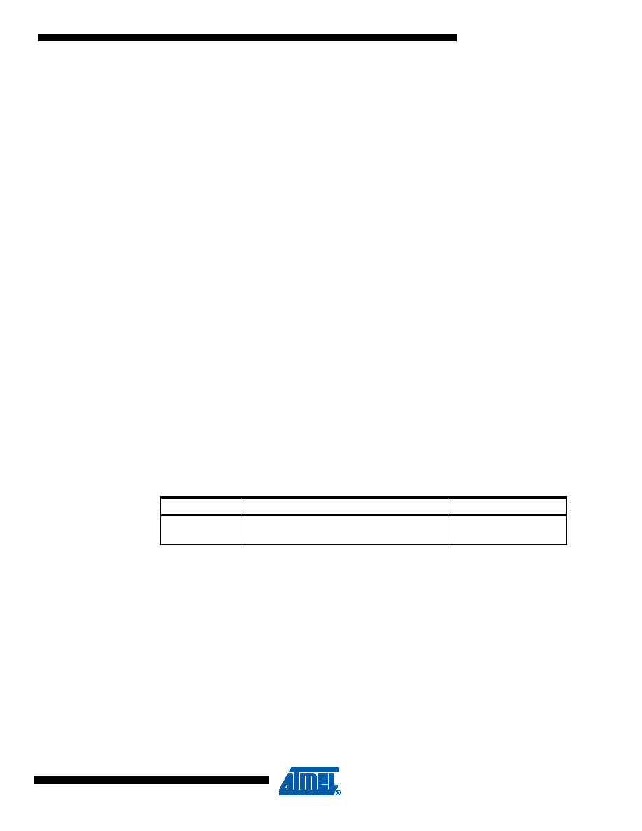
The calibrated Oscillator is used to time the EEPROM accesses. Table 5-2 lists the typical pro-
gramming time for EEPROM access from the CPU.
The following code examples show one assembly and one C function for writing to the
EEPROM. The examples assume that interrupts are controlled (e.g. by disabling interrupts glob-
ally) so that no interrupts will occur during execution of these functions. The examples also
Table 5-2.
EEPROM Programming Time
Symbol
Number of Calibrated RC Oscillator Cycles
Typ Programming Time
EEPROM write
(from CPU)
26,368
3.3 ms
相关PDF资料 |
PDF描述 |
|---|---|
| IF280C52XXX-L16SHXXX | 8-BIT, MROM, 16 MHz, MICROCONTROLLER, PQFP44 |
| IQ80C52CXXX-20SHXXX:D | 8-BIT, MROM, 20 MHz, MICROCONTROLLER, CQFP44 |
| IQ80C52EXXX-30SHXXX | 8-BIT, MROM, 30 MHz, MICROCONTROLLER, CQFP44 |
| IQ80C52XXX-30SHXXX:D | 8-BIT, MROM, 30 MHz, MICROCONTROLLER, CQFP44 |
| IQ80C52XXX-36SHXXX:R | 8-BIT, MROM, 36 MHz, MICROCONTROLLER, CQFP44 |
相关代理商/技术参数 |
参数描述 |
|---|---|
| IF283C151C-12 | 制造商:TEMIC 制造商全称:TEMIC Semiconductors 功能描述:CMOS 0 to 36 MHz Single Chip 8-bit Microcontroller |
| IF283C151C-16 | 制造商:TEMIC 制造商全称:TEMIC Semiconductors 功能描述:CMOS 0 to 36 MHz Single Chip 8-bit Microcontroller |
| IF283C151C-20 | 制造商:TEMIC 制造商全称:TEMIC Semiconductors 功能描述:CMOS 0 to 36 MHz Single Chip 8-bit Microcontroller |
| IF283C151C-25 | 制造商:TEMIC 制造商全称:TEMIC Semiconductors 功能描述:CMOS 0 to 36 MHz Single Chip 8-bit Microcontroller |
| IF283C151C-30 | 制造商:TEMIC 制造商全称:TEMIC Semiconductors 功能描述:CMOS 0 to 36 MHz Single Chip 8-bit Microcontroller |
发布紧急采购,3分钟左右您将得到回复。