- 您现在的位置:买卖IC网 > PDF目录61093 > IL223AT (VISHAY SEMICONDUCTORS) 1 CHANNEL DARLINGTON OUTPUT OPTOCOUPLER PDF资料下载
参数资料
| 型号: | IL223AT |
| 厂商: | VISHAY SEMICONDUCTORS |
| 元件分类: | 光电耦合器 |
| 英文描述: | 1 CHANNEL DARLINGTON OUTPUT OPTOCOUPLER |
| 封装: | ROHS COMPLIANT, SOIC-8 |
| 文件页数: | 2/7页 |
| 文件大小: | 113K |
| 代理商: | IL223AT |
Document Number: 83617
For technical questions, contact: optocoupler.answers@vishay.com
www.vishay.com
Rev. 1.8, 08-May-08
331
IL221AT/222AT/223AT
Optocoupler, Photodarlington Output,
Low Input Current, High Gain, with Base
Connection
Vishay Semiconductors
Note
Tamb = 25 °C, unless otherwise specified.
Stresses in excess of the absolute maximum ratings can cause permanent damage to the device. Functional operation of the device is not implied
at these or any other conditions in excess of those given in the operational sections of this document. Exposure to absolute maximum ratings for
extended periods of the time can adversely affect reliability.
Note
Tamb = 25 °C, unless otherwise specified.
Minimum and maximum values are tested requierements. Typical values are characteristics of the device and are the result of engineering
evaluations. Typical values are for information only and are not part of the testing requirements.
COUPLER
Isolation test voltage
t = 1.0 s
VISO
4000
VRMS
Total package dissipation
(at 25 °C ambient)(LED and detector)
Ptot
240
mW
Derate linearly from 25 °C
3.2
mW/°C
Storage temperature
Tstg
- 55 to + 150
°C
Operating temperature
Tamb
- 55 to + 100
°C
Soldering time at 260 °C
10
s
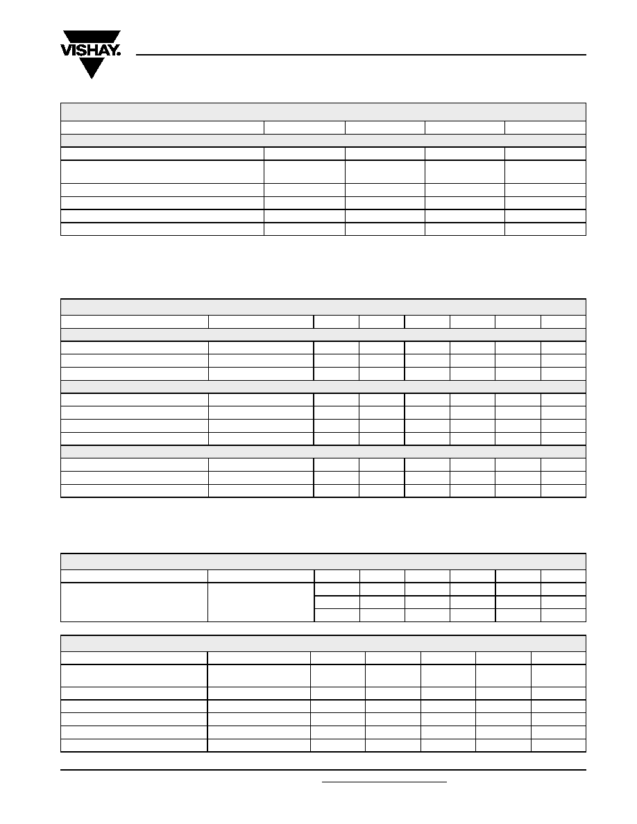
ELECTRICAL CHARACTERISTCS
PARAMETER
TEST CONDITION
PART
SYMBOL
MIN.
TYP.
MAX.
UNIT
INPUT
Forward voltage
IF = 1.0 mA
VF
1.0
1.5
V
Reverse current
VR = 6 V
IR
0.1
100
A
Capacitance
VR = 0 V, f = 1.0 MHz
CO
25
pF
OUTPUT
Collector emitter breakdown voltage
IC = 100 A
BVCEO
30
V
Emitter collector breakdown voltage
IE = 100 A
BVECO
5.0
V
Emitter emitter breakdown voltage
IC = 10 A
BVCBO
70
V
Collector emitter capacitance
VCE = 10 V
CCE
3.4
pF
COUPLER
Saturation voltage, collector emitter
ICE = 0.5 mA
VCEsat
1.0
V
Capacitance (input to output)
CIO
0.5
pF
Resistance (input to output)
RIO
100
G
Ω
CURRENT TRANSFER RATIO
PARAMETER
TEST CONDITION
PART
SYMBOL
MIN.
TYP.
MAX.
UNIT
Current transfer ratio
IF = 1.0 mA, VCE = 5.0 V
IL221AT
CTRDC
100
%
IL222AT
CTRDC
200
%
IL223AT
CTRDC
500
%
SAFETY AND INSULATION RATINGS
PARAMETER
TEST CONDITION
SYMBOL
MIN.
TYP.
MAX.
UNIT
Climatic classification
(according to IEC 68 part 1)
55/100/21
Comparative tracking index
CTI
175
399
VIOTM
6000
V
VIORM
560
V
PSO
350
mW
ISI
150
mA
ABSOLUTE MAXIMUM RATINGS
PARAMETER
TEST CONDITION
SYMBOL
VALUE
UNIT
相关PDF资料 |
PDF描述 |
|---|---|
| IL223A | 1 CHANNEL DARLINGTON OUTPUT OPTOCOUPLER |
| IL222A | 1 CHANNEL DARLINGTON OUTPUT OPTOCOUPLER |
| IL255-1-X001 | 1 CHANNEL AC INPUT-TRANSISTOR OUTPUT OPTOCOUPLER |
| IL255 | 1 CHANNEL AC INPUT-TRANSISTOR OUTPUT OPTOCOUPLER |
| IL255-2-X001 | 1 CHANNEL AC INPUT-TRANSISTOR OUTPUT OPTOCOUPLER |
相关代理商/技术参数 |
参数描述 |
|---|---|
| IL223AT | 制造商:Vishay Semiconductors 功能描述:OPTOCOUPLER |
| IL223T | 制造商:未知厂家 制造商全称:未知厂家 功能描述:Optoelectronic |
| IL230N252 | 制造商:EGS ELECTRICAL GROUP 功能描述:IL-2 230V SINGL 2W+6 25KA |
| IL230N50 | 制造商:Sola/Hevi-Duty 功能描述: |
| IL230X100 | 制造商:Sola/Hevi-Duty 功能描述: |
发布紧急采购,3分钟左右您将得到回复。