- 您现在的位置:买卖IC网 > PDF目录1925 > IL3522E (NVE Corp/Isolation Products)IC DIFFER BUS TRANSC 16 SOIC PDF资料下载
参数资料
| 型号: | IL3522E |
| 厂商: | NVE Corp/Isolation Products |
| 文件页数: | 14/15页 |
| 文件大小: | 0K |
| 描述: | IC DIFFER BUS TRANSC 16 SOIC |
| 产品培训模块: | IsoLoop® Isolator |
| 标准包装: | 50 |
| 系列: | IsoLoop® |
| 类型: | 收发器,隔离式 |
| 驱动器/接收器数: | 1/1 |
| 规程: | RS422 |
| 电源电压: | 3 V ~ 5.5 V,4.5 V ~ 5.5 V |
| 安装类型: | 表面贴装 |
| 封装/外壳: | 16-SOIC(0.295",7.50mm 宽) |
| 供应商设备封装: | 16-SOIC |
| 包装: | 管件 |
| 其它名称: | Q3077370 |
IL3522
8
NVE Corporation
11409 Valley View Road, Eden Prairie, MN 55344-3617
Phone: (952) 829-9217
Fax: (952) 829-9189
www.IsoLoop.com
NVE Corporation
Electrostatic Discharge Sensitivity
This product has been tested for electrostatic sensitivity to the limits stated in the specifications. However, NVE recommends that all integrated
circuits be handled with appropriate care to avoid damage. Damage caused by inappropriate handling or storage could range from performance
degradation to complete failure.
Power Consumption
IsoLoop Isolators achieve their low power consumption from the way they transmit data across the isolation barrier. By detecting the edge
transitions of the input logic signal and converting these to narrow current pulses, a magnetic field is created around the GMR Wheatstone
bridge. Depending on the direction of the magnetic field, the bridge causes the output comparator to switch following the input logic signal.
Since the current pulses are narrow, about 2.5 ns, the power consumption is independent of mark-to-space ratio and solely dependent on
frequency. This has obvious advantages over optocouplers, which have power consumption heavily dependent on frequency and time.
Data Rate (Mbps)
IDD1
IDD2
1
100 μA
10
1 mA
20
2 mA
40
4 mA
Table 2. Typical Dynamic Supply Currents.
Power Supply Decoupling
Both VDD1 and VDD2 must be bypassed with 47 nF ceramic capacitors. These should be placed as close as possible to VDD pins for proper
operation. Additionally, VDD2 should be bypassed with a 10 F tantalum capacitor.
Maintaining Creepage
Creepage distances are often critical in isolated circuits. In addition to meeting JEDEC standards, NVE isolator packages have unique creepage
specifications. Standard pad libraries often extend under the package, compromising creepage and clearance. Similarly, ground planes, if used,
should be spaced to avoid compromising clearance. Package drawings and recommended pad layouts are included in this datasheet.
DC Correctness
The IL3522 incorporates a patented refresh circuit to maintain the correct output state with respect to data input. At power up, the bus outputs
will follow the Function Table shown on Page 1. The DE input should be held low during power-up to eliminate false drive data pulses from the
bus. An external power supply monitor to minimize glitches caused by slow power-up and power-down transients is not required.
Electromagnetic Compatibility
The IL3522 is fully compliant with generic EMC standards EN50081, EN50082-1 and the umbrella line-voltage standard for Information
Technology Equipment (ITE) EN61000. The IsoLoop Isolator’s Wheatstone bridge configuration and differential magnetic field signaling ensure
excellent EMC performance against all relevant standards. NVE conducted compliance tests in the categories below:
EN50081-1
Residential, Commercial & Light Industrial
Methods EN55022, EN55014
EN50082-2: Industrial Environment
Methods EN61000-4-2 (ESD), EN61000-4-3 (Electromagnetic Field Immunity), EN61000-4-4 (Electrical Transient Immunity),
EN61000-4-6 (RFI Immunity), EN61000-4-8 (Power Frequency Magnetic Field Immunity), EN61000-4-9 (Pulsed Magnetic
Field), EN61000-4-10 (Damped Oscillatory Magnetic Field)
ENV50204
Radiated Field from Digital Telephones (Immunity Test)
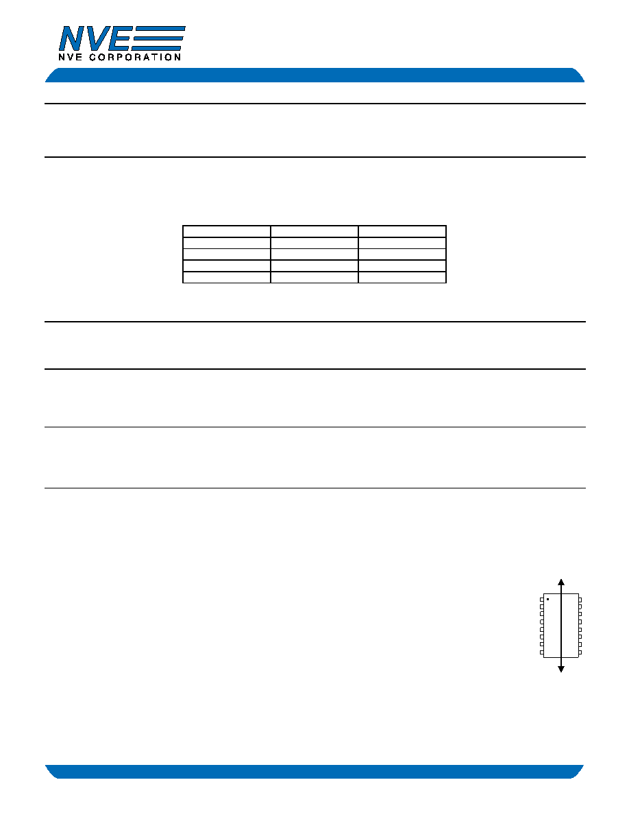
Immunity to external magnetic fields is even higher if the field direction is “end-to-end” (rather than to “pin-to-pin”) as shown in
the diagram at right.
相关PDF资料 |
PDF描述 |
|---|---|
| IL3585 | ISOLATOR PROFIB 485 XCVR 16SOICW |
| IL3685E | PROFIBUS RS-485 INTERFACE ISO |
| IL41050TE | IC TXRX ISOLATED CAN HS 16SOIC |
| IL422-3V | ISOLATOR HS MAGNETC RS422 16SOIC |
| IL485E-3V | ISOLATOR HS MAG DIGITAL 16SOICW |
相关代理商/技术参数 |
参数描述 |
|---|---|
| IL3522ETR13 | 功能描述:IC DIFFER BUS TRANSC 16 SOIC RoHS:是 类别:集成电路 (IC) >> 接口 - 驱动器,接收器,收发器 系列:IsoLoop® 标准包装:1,240 系列:GD 类型:收发器 驱动器/接收器数:3/5 规程:RS232 电源电压:4.5 V ~ 5.5 V 安装类型:通孔 封装/外壳:20-DIP(0.300",7.62mm) 供应商设备封装:20-PDIP 包装:管件 |
| IL3522VE | 功能描述:RS422, RS485 Digital Isolator 6000Vrms 3 Channel 40Mbps 30kV/μs CMTI 16-SOIC (0.295", 7.50mm Width) 制造商:nve corp/isolation products 系列:IsoLoop? 包装:管件 零件状态:有效 技术:GMR(大型磁阻传感) 类型:RS422,RS485 隔离式电源:无 通道数:3 输入 - 输入侧 1/输入侧 2:2/1 通道类型:单向 电压 - 隔离:6000Vrms 共模瞬态抗扰度(最小值):30kV/μs 数据速率:40Mbps 传播延迟 tpLH / tpHL(最大值):35ns,35ns 脉宽失真(最大):- 上升/下降时间(典型值):- 电压 - 电源:3 V ~ 5.5 V,4.5 V ~ 5.5 V 工作温度:-40°C ~ 85°C 封装/外壳:16-SOIC(0.295",7.50mm 宽) 供应商器件封装:16-SOIC 标准包装:50 |
| IL356 | 制造商:INFINEON 制造商全称:Infineon Technologies AG 功能描述:HIGH VOLTAGE SOLID STATE RELA OPTOCOUPLER |
| IL358 | 功能描述:高线性光耦合器 Linear for Optical DAA in Telecomm RoHS:否 制造商:Avago Technologies 输入类型:AC/DC 最大正向二极管电压:1.95 V 最大反向二极管电压:2.5 V 最大输入二极管电流:25 mA 最大功率耗散:60 mW 最大工作温度:+ 100 C 最小工作温度:- 55 C 封装 / 箱体:DIP-8 Gull Wing 封装:Tube |
| IL358_11 | 制造商:IKSEMICON 制造商全称:IK Semicon Co., Ltd 功能描述:Low Power Dual Operational Amplifier |
发布紧急采购,3分钟左右您将得到回复。