参数资料
| 型号: | IP82C54 |
| 厂商: | Intersil |
| 文件页数: | 2/22页 |
| 文件大小: | 0K |
| 描述: | IC OSC PROG TIMER 8MHZ 24DIP |
| 标准包装: | 165 |
| 类型: | 可编程计时器 |
| 频率: | 8MHz |
| 电源电压: | 4.5 V ~ 5.5 V |
| 电流 - 电源: | 10mA |
| 工作温度: | -40°C ~ 85°C |
| 封装/外壳: | 24-DIP(0.600",15.24mm) |
| 包装: | 管件 |
| 供应商设备封装: | 24-PDIP |
| 安装类型: | 通孔 |
10
82C54
the counters selected by setting their corresponding bits D3,
D2, D1 = 1.
The read-back command may be used to latch multiple
counter output latches (OL) by setting the COUNT bit D5 = 0
and selecting the desired counter(s). This signal command is
functionally equivalent to several counter latch commands,
one for each counter latched. Each counter’s latched count
is held until it is read (or the counter is reprogrammed). That
counter is automatically unlatched when read, but other
counters remain latched until they are read. If multiple count
read-back commands are issued to the same counter
without reading the count, all but the first are ignored; i.e.,
the count which will be read is the count at the time the first
read-back command was issued.
The read-back command may also be used to latch status
information of selected counter(s) by setting STATUS bit D4
= 0. Status must be latched to be read; status of a counter is
accessed by a read from that counter.
The counter status format is shown in Figure 6. Bits D5
through D0 contain the counter’s programmed Mode exactly
as written in the last Mode Control Word. OUTPUT bit D7
contains the current state of the OUT pin. This allows the
user to monitor the counter’s output via software, possibly
eliminating some hardware from a system.
NULL COUNT bit D6 indicates when the last count written to
the counter register (CR) has been loaded into the counting
element (CE). The exact time this happens depends on the
Mode of the counter and is described in the Mode Definitions,
but until the counter is loaded into the counting element (CE),
it can’t be read from the counter. If the count is latched or read
before this time, the count value will not reflect the new count
just written. The operation of Null Count is shown below.
THIS ACTION:
CAUSES:
A. Write to the control word register:(1) . . . . Null Count = 1
B. Write to the count register (CR):(2) . . . . . Null Count = 1
C. New count is loaded into CE (CR - CE) . . Null Count = 0
1. Only the counter specified by the control word will have
its null count set to 1. Null count bits of other counters are
unaffected.
2. If the counter is programmed for two-byte counts (least
significant byte then most significant byte) null count goes
to 1 when the second byte is written.
If multiple status latch operations of the counter(s) are
performed without reading the status, all but the first are
ignored; i.e., the status that will be read is the status of the
counter at the time the first status read-back command was
issued.
Both count and status of the selected counter(s) may be
latched simultaneously by setting both COUNT and
STATUS bits D5, D4 = 0. This is functionally the same as
issuing two separate read-back commands at once, and the
above discussions apply here also. Specifically, if multiple
count and/or status read-back commands are issued to the
same counter(s) without any intervening reads, all but the
first are ignored. This is illustrated in Figure 7.
If both count and status of a counter are latched, the first
read operation of that counter will return latched status,
regardless of which was latched first. The next one or two
reads (depending on whether the counter is programmed for
one or two type counts) return latched count. Subsequent
reads return unlatched count.
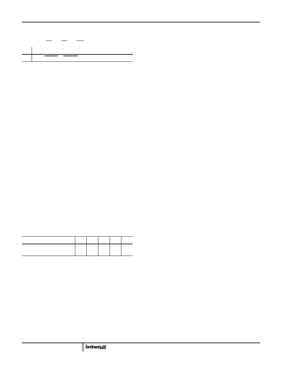
A0, A1 = 11; CS = 0; RD = 1; WR = 0
D7
D6
D5
D4
D3
D2
D1
D0
1
COUNT
STATUS CNT 2CNT 1CNT 0
0
D5:0=Latch count of selected Counter (s)
D4:0=Latch status of selected Counter(s)
D3:1=Select Counter 2
D2:1=Select Counter 1
D1:1=Select Counter 0
D0:Reserved for future expansion; Must be 0
FIGURE 5. READ-BACK COMMAND FORMAT
D7
D6
D5
D4
D3
D2
D1
D0
OUTPUT
NULL
COUNT
RW1 RW0
M2
M1
M0
BCD
D7:1=Out pin is 1
0=Out pin is 0
D6:1=Null count
0=Count available for reading
D5-D0=Counter programmed mode (See Control Word Formats)
FIGURE 6. STATUS BYTE
相关PDF资料 |
PDF描述 |
|---|---|
| CS82C54-12 | IC OSC PROG TIMER 12MHZ 28PLCC |
| VE-BTP-MX-B1 | CONVERTER MOD DC/DC 13.8V 75W |
| VE-B4B-IU-F1 | CONVERTER MOD DC/DC 95V 200W |
| VE-BTN-MX-B1 | CONVERTER MOD DC/DC 18.5V 75W |
| VE-B44-IU-F3 | CONVERTER MOD DC/DC 48V 200W |
相关代理商/技术参数 |
参数描述 |
|---|---|
| IP82C54/+ | 制造商:未知厂家 制造商全称:未知厂家 功能描述:Analog Timer Circuit |
| IP82C54-10 | 功能描述:计时器和支持产品 PERIPH PRG-CNTR 5V 10MHZ 24PDIP IND RoHS:否 制造商:Micrel 类型:Standard 封装 / 箱体:SOT-23 内部定时器数量:1 电源电压-最大:18 V 电源电压-最小:2.7 V 最大功率耗散: 最大工作温度:+ 85 C 最小工作温度:- 40 C 封装:Reel |
| IP82C54-10S5001 | 制造商:Rochester Electronics LLC 功能描述:- Bulk |
| IP82C54-10Z | 功能描述:计时器和支持产品 W/ANNEAL PERIPH PRG- CNTR 5V 10MHZ 24PDIP RoHS:否 制造商:Micrel 类型:Standard 封装 / 箱体:SOT-23 内部定时器数量:1 电源电压-最大:18 V 电源电压-最小:2.7 V 最大功率耗散: 最大工作温度:+ 85 C 最小工作温度:- 40 C 封装:Reel |
| IP82C54-12 | 制造商:INTERSIL 制造商全称:Intersil Corporation 功能描述:CMOS Programmable Interval Timer |
发布紧急采购,3分钟左右您将得到回复。