- 您现在的位置:买卖IC网 > PDF目录377498 > IR21571S (International Rectifier) FULLY INTEGRATED BALLAST CONTROL IC PDF资料下载
参数资料
| 型号: | IR21571S |
| 厂商: | International Rectifier |
| 英文描述: | FULLY INTEGRATED BALLAST CONTROL IC |
| 中文描述: | 完全集成的镇流器控制IC |
| 文件页数: | 8/17页 |
| 文件大小: | 234K |
| 代理商: | IR21571S |
IR21571
(S)
8
www.irf.com
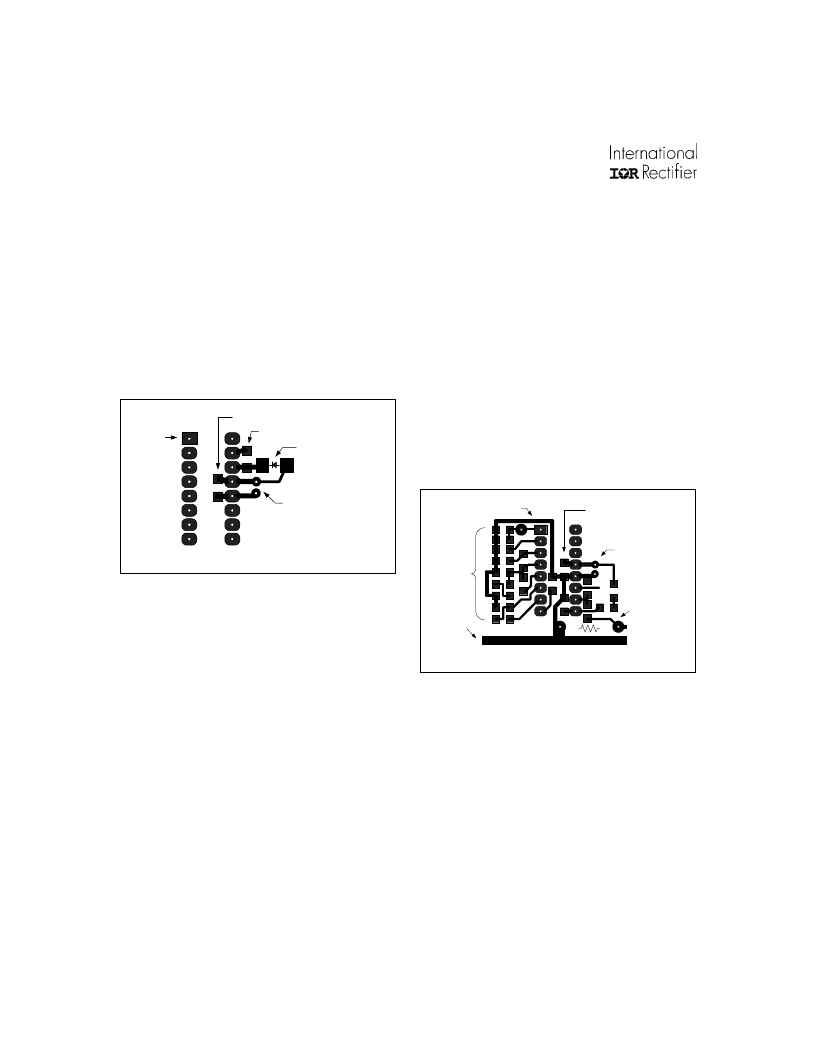
Supply Bypassing and PC Board
Layout Rules
Component selection and placement on the pc
board is extremely important when using power
control ICs. V
CC
should be bypassed to COM as close
to the IC terminals as possible with a low ESR/ESL
capacitor, as shown in Figure 1 below.
A rule of thumb for the value of this bypass capacitor
is to keep its minimum value at least 2500 times the
value of the total input capacitance (Ciss) of the
power transistors being driven. This decoupling
capacitor can be split between a higher valued
electrolytic type and a lower valued ceramic type
connected in parallel, although a good quality
electrolytic (e.g., 10
μ
F) placed immediately adjacent
to the V
CC
and COM terminals will work well.
In a typical application circuit, the supply voltage to
the IC is normally derived by means of a high value
startup resistor (1/4W) from the rectified line voltage,
in combination with a charge pump from the output
of the half-bridge. With this type of supply
arrangement, the internal 15.6V zener clamp diode
from V
CC
to COM will determine the steady state IC
supply voltage.
Connecting the IC Ground (COM)
to the Power Ground
Both the low power control circuitry and low side
gate driver output stage grounds return to this lead
within the IC. The COM lead should be connected to
the bottom terminal of the current sense resistor in
the source of the low side power MOSFET using an
individual pc board trace, as shown in Figure 2. In
addition, the ground return path of the timing
components and V
CC
decoupling capacitor should
be connected directly to the IC COM lead, and not
via separate traces or jumpers to other ground traces
on the board.
This connection technique prevents high current
ground loops from interfering with the sensitive timing
component operation, and allows the entire control
circuit to reject common-mode noise due to output
switching.
Description of Operation & Component Selection Tips
Figure 1: Supply bypassing PCB layout example
Figure 2: COM lead connection PCB layout example
C
VCC
(surface mount)
D
Boot
(surface mount)
C
BOOT
(surface mount)
C
VCC
(through hole)
pin 1
IR21571
C
VCC
(surface mount)
C
VCC
(through hole)
IR21571
pin 1
timing
components
V
BUS
return
R
CS
(through hole)
相关PDF资料 |
PDF描述 |
|---|---|
| IR21571 | FULLY INTEGRATED BALLAST CONTROL IC |
| IR21593 | DIMMING BALLAST CONTROL IC |
| IR21593S | DIMMING BALLAST CONTROL IC |
| IR21592 | DIMMING BALLAST CONTROL IC |
| IR21592S | DIMMING BALLAST CONTROL IC |
相关代理商/技术参数 |
参数描述 |
|---|---|
| IR21571SPBF | 功能描述:功率驱动器IC BALLAST CTRL BELO 600V 15.6V VCC 150uA RoHS:否 制造商:Micrel 产品:MOSFET Gate Drivers 类型:Low Cost High or Low Side MOSFET Driver 上升时间: 下降时间: 电源电压-最大:30 V 电源电压-最小:2.75 V 电源电流: 最大功率耗散: 最大工作温度:+ 85 C 安装风格:SMD/SMT 封装 / 箱体:SOIC-8 封装:Tube |
| IR21571STR | 功能描述:IC BALLAST CONTROL INTEG 16-SOIC RoHS:否 类别:集成电路 (IC) >> PMIC - 照明,镇流器控制器 系列:- 产品培训模块:Lead (SnPb) Finish for COTS Obsolescence Mitigation Program 标准包装:2,500 系列:- 类型:CCFL 控制器 频率:40 ~ 80 kHz 电流 - 电源:5mA 电流 - 输出:- 电源电压:4.5 V ~ 5.5 V 工作温度:-40°C ~ 85°C 封装/外壳:16-SOIC(0.154",3.90mm 宽) 供应商设备封装:16-SOIC 包装:带卷 (TR) 其它名称:90-3991V+V01 |
| IR21571STRPBF | 功能描述:功率驱动器IC Ballast Cntrl Thrml Ovrload Prot RoHS:否 制造商:Micrel 产品:MOSFET Gate Drivers 类型:Low Cost High or Low Side MOSFET Driver 上升时间: 下降时间: 电源电压-最大:30 V 电源电压-最小:2.75 V 电源电流: 最大功率耗散: 最大工作温度:+ 85 C 安装风格:SMD/SMT 封装 / 箱体:SOIC-8 封装:Tube |
| IR2157S | 制造商:未知厂家 制造商全称:未知厂家 功能描述:Ballast Control. Below Resonance Protection. Thermal Overload Protection. Protection from Failure to Strike. Programmable Preheat Time and Run Frequency. Programmable Deadtime in a 16-lead SOIC Narrow package |
| IR2159 | 制造商:IRF 制造商全称:International Rectifier 功能描述:DIMMING BALLAST CONTROL IC |
发布紧急采购,3分钟左右您将得到回复。