- 您现在的位置:买卖IC网 > PDF目录377498 > IR21571S (International Rectifier) FULLY INTEGRATED BALLAST CONTROL IC PDF资料下载
参数资料
| 型号: | IR21571S |
| 厂商: | International Rectifier |
| 英文描述: | FULLY INTEGRATED BALLAST CONTROL IC |
| 中文描述: | 完全集成的镇流器控制IC |
| 文件页数: | 9/17页 |
| 文件大小: | 234K |
| 代理商: | IR21571S |
IR21571
(S)
www.irf.com
9
The Control Sequence & Timing
Component Selection
The IR21571 uses the following control sequence
(Figure 3) to drive rapid start fluorescent lamps.
The control sequence used in the IR21571 allows
the Run Mode operating frequency of the ballast to
be higher than the ignition frequency (i.e., fstart >
fph > frun > fign). This control sequence is
recommended for lamp types where the ignition
frequency is too close to the run frequency to ensure
proper lamp striking for all production resonant LC
component tolerances (please note that it is possible
to use the IR21571 in systems where fstart > fph >
fign > frun, simply by leaving the RUN lead open).
Six leads in the IC are used to control the
Startup,
Preheat, Ignition Ramp,
and
Run
modes of
operation, and to allow ballast and lamp engineers
the flexibility to optimize their designs for virtually
any lamp type.
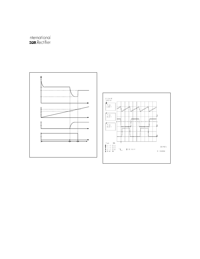
The heart of this controller is an oscillator which
resembles those found in many popular PWM voltage
regulator ICs. In its simplest form, this oscillator
consists of a timing resistor and capacitor connected
to ground. The voltage across the timing capacitor
CT is a sawtooth, where the rising portion of the ramp
is determined by the current in the R
T
lead, and the
falling portion of the ramp is determined by an external
deadtime resistor R
DT
. The oscillograph in Figure 4
illustrates the relationship between the oscillator
capacitor waveform and the gate driver outputs.
The deadtime can be programmed by means of the
external R
DT
resistor, given a certain range of CT
capacitor values, using the graph shown in Figure 5.
The R
T
input is a voltage-controlled current source,
where the voltage is regulated to be approximately
2.0V. In order to maintain proper linearity between
the R
T
lead current and the C
T
capacitor charging
current, the value of the R
T
lead current should be
kept between 50μA and 500μA. The R
T
lead can
also be used as a feedback point for closed loop
control.
Figure 3: IR21571 control sequence
Figure 4
f
PH
f
Run
f
min
f
t
f
Start
V
CPH
5V
V
RPH
2V
V
RUN
2V
Preheat mode
Ignition
Ramp
mode
Run mode
相关PDF资料 |
PDF描述 |
|---|---|
| IR21571 | FULLY INTEGRATED BALLAST CONTROL IC |
| IR21593 | DIMMING BALLAST CONTROL IC |
| IR21593S | DIMMING BALLAST CONTROL IC |
| IR21592 | DIMMING BALLAST CONTROL IC |
| IR21592S | DIMMING BALLAST CONTROL IC |
相关代理商/技术参数 |
参数描述 |
|---|---|
| IR21571SPBF | 功能描述:功率驱动器IC BALLAST CTRL BELO 600V 15.6V VCC 150uA RoHS:否 制造商:Micrel 产品:MOSFET Gate Drivers 类型:Low Cost High or Low Side MOSFET Driver 上升时间: 下降时间: 电源电压-最大:30 V 电源电压-最小:2.75 V 电源电流: 最大功率耗散: 最大工作温度:+ 85 C 安装风格:SMD/SMT 封装 / 箱体:SOIC-8 封装:Tube |
| IR21571STR | 功能描述:IC BALLAST CONTROL INTEG 16-SOIC RoHS:否 类别:集成电路 (IC) >> PMIC - 照明,镇流器控制器 系列:- 产品培训模块:Lead (SnPb) Finish for COTS Obsolescence Mitigation Program 标准包装:2,500 系列:- 类型:CCFL 控制器 频率:40 ~ 80 kHz 电流 - 电源:5mA 电流 - 输出:- 电源电压:4.5 V ~ 5.5 V 工作温度:-40°C ~ 85°C 封装/外壳:16-SOIC(0.154",3.90mm 宽) 供应商设备封装:16-SOIC 包装:带卷 (TR) 其它名称:90-3991V+V01 |
| IR21571STRPBF | 功能描述:功率驱动器IC Ballast Cntrl Thrml Ovrload Prot RoHS:否 制造商:Micrel 产品:MOSFET Gate Drivers 类型:Low Cost High or Low Side MOSFET Driver 上升时间: 下降时间: 电源电压-最大:30 V 电源电压-最小:2.75 V 电源电流: 最大功率耗散: 最大工作温度:+ 85 C 安装风格:SMD/SMT 封装 / 箱体:SOIC-8 封装:Tube |
| IR2157S | 制造商:未知厂家 制造商全称:未知厂家 功能描述:Ballast Control. Below Resonance Protection. Thermal Overload Protection. Protection from Failure to Strike. Programmable Preheat Time and Run Frequency. Programmable Deadtime in a 16-lead SOIC Narrow package |
| IR2159 | 制造商:IRF 制造商全称:International Rectifier 功能描述:DIMMING BALLAST CONTROL IC |
发布紧急采购,3分钟左右您将得到回复。