- 您现在的位置:买卖IC网 > PDF目录1809 > IR3651STRPBF (International Rectifier)IC REG CTRLR BUCK PWM VM 14-SOIC PDF资料下载
参数资料
| 型号: | IR3651STRPBF |
| 厂商: | International Rectifier |
| 文件页数: | 14/19页 |
| 文件大小: | 0K |
| 描述: | IC REG CTRLR BUCK PWM VM 14-SOIC |
| 标准包装: | 2,500 |
| PWM 型: | 电压模式 |
| 输出数: | 1 |
| 频率 - 最大: | 460kHz |
| 占空比: | 80% |
| 电源电压: | 4.5 V ~ 13.2 V |
| 降压: | 是 |
| 升压: | 无 |
| 回扫: | 无 |
| 反相: | 无 |
| 倍增器: | 无 |
| 除法器: | 无 |
| Cuk: | 无 |
| 隔离: | 无 |
| 工作温度: | 0°C ~ 125°C |
| 封装/外壳: | 14-SOIC(0.154",3.90mm 宽) |
| 包装: | 带卷 (TR) |
| 配用: | IRDC3651-ND - KIT REF DESIGN SYNCH BUCK REG |
�� �
�
�IR3651SPBF�
�Power� MOSFET� Selection�
�The� IR3651� uses� two� N-Channel� MOSFETs.� The�
�selections� criteria� to� meet� power� transfer�
�requirements� is� based� on� maximum� drain-source�
�voltage� (V� DSS� ),� gate-source� drive� voltage� (V� gs� ),�
�maximum� output� current,� On-resistance� R� DS(on)�
�and� thermal� management.�
�switching� losses� in� synchronous� Buck� converter.�
�The� synchronous� MOSFET� turns� on� under� zero�
�voltage� conditions,� therefore,� the� turn� on� losses�
�for� synchronous� MOSFET� can� be� neglected.�
�With� a� linear� approximation,� the� total� switching�
�loss� can� be� expressed� as:�
�V� ds� (� off� )� t� r� +� t� f�
�The� MOSFET� must� have� a� maximum� operating�
�voltage� (V� DSS� )� exceeding� the� maximum� input�
�P� sw� =�
�2� T�
�*�
�*� I� load�
�-� -(10)�
�voltage� (V� in� ).�
�The� gate� drive� requirement� is� almost� the� same�
�for� both� MOSFETs.� Logic-level� transistor� can� be�
�used� and� caution� should� be� taken� with� devices� at�
�very� low� V� gs� to� prevent� undesired� turn-on� of� the�
�complementary� MOSFET,� which� results� in� shoot-�
�through� current.�
�The� total� power� dissipation� for� MOSFETs�
�includes� conduction� and� switching� losses.� For�
�the� Buck� converter� the� average� inductor� current�
�is� equal� to� the� DC� load� current.� The� conduction�
�loss� is� defined� as:�
�Where:�
�V� ds(off)� =� Drain� to� source� voltage� at� the� off� time�
�t� r� =� Rise� time�
�t� f� =� Fall� time�
�T� =� Switching� period�
�I� load� =� Load� current�
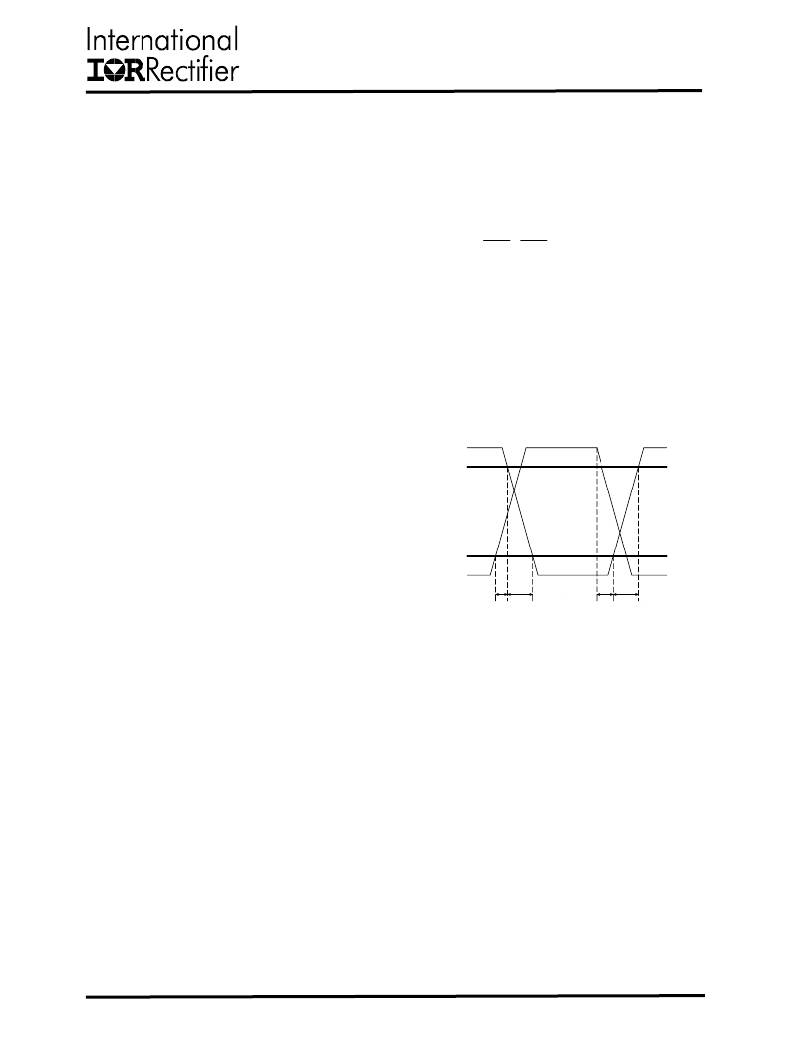
�The� switching� time� waveforms� is� shown� in�
�figure10.�
�V� DS�
�P� cond� =� (upper� switch)� =� I�
�P� cond� =� (lower� switch)� =� I�
�2�
�load�
�2�
�load�
�?� R� ds(on)� ?� D� ?� ?�
�?� R� ds(on)� ?� (1� ?� D)� ?� ?�
�90%�
�?� =� R� ds(on)� temperatur� e� dependency�
�The� R� DS(on)� temperature� dependency� should� be�
�considered� for� the� worst� case� operation.� This� is�
�typically� given� in� the� MOSFET� data� sheet.�
�10%�
�V� GS�
�Ensure� that� the� conduction� losses� and� switching�
�t� d� (ON)�
�t� r�
�t� d� (OFF)�
�t� f�
�losses� do� not� exceed� the� package� ratings� or�
�violate� the� overall� thermal� budget.�
�The� switching� loss� is� more� difficult� to� calculate,�
�even� though� the� switching� transition� is� well�
�understood.� The� reason� is� the� effect� of� the�
�parasitic� components� and� switching� times� during�
�the� switching� procedures� such� as� turn-on� /� turn-�
�off� delays� and� rise� and� fall� times.� The� control�
�MOSFET� contributes� to� the� majority� of� the�
�06/08/2011�
�Fig.� 10:� switching� time� waveforms�
�14�
�相关PDF资料 |
PDF描述 |
|---|---|
| IR3710MTRPBF | IC REG CTRLR BUCK PWM 16-MLPQ |
| IR3720MTRPBF | IC POWER SUPPLY MONITOR 10-DFN |
| IR3721MTRPBF | IC POWER SUPPLY MONITOR 10-DFN |
| IR3725MTRPBF | IC PWR MONITOR INPUT 12-DFN |
| IR3800AMTRPBF | IC REG BUCK SYNC ADJ 14A 15QFN |
相关代理商/技术参数 |
参数描述 |
|---|---|
| IR3651STRPBF-CUT TAPE | 制造商:IR 功能描述:IR3651SPbF Series 13.2 V 7 mA High Voltage Synchronous PWM Buck Controller |
| IR367319 | 制造商:Thomas & Betts 功能描述:CONNECTOR |
| IR3702 | 制造商:未知厂家 制造商全称:未知厂家 功能描述:Analog IC |
| IR3702N | 制造商:未知厂家 制造商全称:未知厂家 功能描述:Analog IC |
| IR370BGD | 制造商:未知厂家 制造商全称:未知厂家 功能描述: |
发布紧急采购,3分钟左右您将得到回复。