- 您现在的位置:买卖IC网 > PDF目录11818 > IS82C52Z96 (Intersil)IC CTRLR CMOS SERIAL 28-PLCC PDF资料下载
参数资料
| 型号: | IS82C52Z96 |
| 厂商: | Intersil |
| 文件页数: | 20/20页 |
| 文件大小: | 0K |
| 描述: | IC CTRLR CMOS SERIAL 28-PLCC |
| 标准包装: | 750 |
| 特点: | 单芯片 UART/BRG |
| 通道数: | 1,UART |
| 规程: | RS232C |
| 电源电压: | 4.5 V ~ 5.5 V |
| 带并行端口: | 是 |
| 带故障启动位检测功能: | 是 |
| 带调制解调器控制功能: | 是 |
| 带CMOS: | 是 |
| 安装类型: | 表面贴装 |
| 封装/外壳: | 28-LCC(J 形引线) |
| 供应商设备封装: | 28-PLCC(11.51x11.51) |
| 包装: | 带卷 (TR) |
9
FN2950.3
April 26, 2006
transmission. The transmitter always has the same word
length and number of stop bits as the receiver. For words of
less than 8 bits the unused bits at the microprocessor data
bus are ignored by the transmitter.
Bit 0, which corresponds to D0 at the data bus, is always the
first serial data bit transmitted. Provision is made for the
transmitter parity to be the same or different from the
receiver. The TBRE output pin and flag (USR register) reflect
the status of the TBR. The TC flag (USR register) indicates
when both TBR and TR are empty.
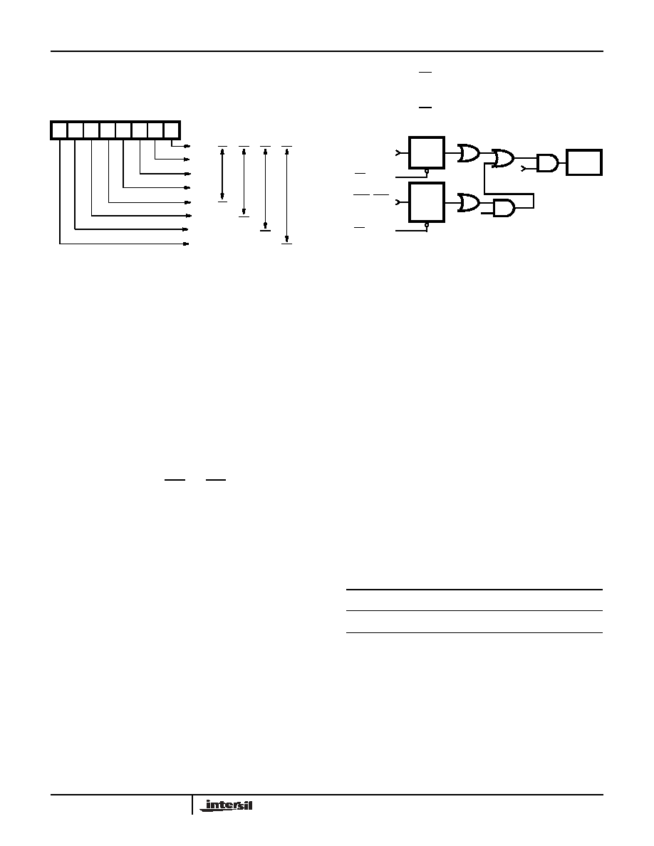
82C52 Interrupt Structure
The 82C52 has provisions for software masking of interrupts
generated for the INTR output pin. Two control bits in the
MCR register, MIEN and INTEN, control modem status
interrupts and overall 82C52 interrupts respectively. Figure 9
illustrates the logical control function provided by these
signals.
The modem status inputs (DSR and CTS) will trigger the
edge detection circuitry with any change of status. Reading
the MSR register will clear the detect circuit but has no effect
on the status bits themselves. These status bits always
reflect the state of the input pins regardless of the mask
control signals. Note that the state (high or low) of the status
bits are inverted versions of the actual input pins.
The edge detection circuits for the USR register signals will
trigger only for a positive edge (true assertion) of these
status bits. Reading the USR register not only clears the
edge detect circuit but also clears (sets to 0) all of the status
bits. The output pins associated with these status bits are not
affected by reading the USR register.
A hardware reset of the 82C52 sets the TC status bit in the
USR. When interrupts are subsequently enabled an interrupt
can occur due to the fact that the positive edge detection
circuitry in the interrupt logic has detected the setting of the
TC bit. If this interrupt is not desired the USR should be read
prior to enabling interrupts. This action resets the positive
edge detection circuitry in the interrupt control logic (Figure 9).
NOTE: For USR and MSR, the setting of status bits is inhibited
during status register READ operations. If a status condition is
generated during a READ operation, the status bit is not set until the
trailing edge of the RD pulse.
If the bit was already set at the time of the READ operation, and the
same status condition occurs, that status bit will be cleared at the
trailing edge of the RD pulse instead of being set again.
Software Reset
A software reset of the 82C52 is a useful method for
returning to a completely known state without exercising a
complete system reset. Such a reset would consist of writing
to the UCR, BRSR and MCR registers. The USR and RBR
registers should be read prior to enabling interrupts in order
to clear out any residual data or status bits which may be
invalid for subsequent operation.
Crystal Operation
The 82C52 crystal oscillator circuitry is designed to operate
with a fundamental mode, parallel resonant crystal. This
circuit is the same one used in the Intersil 82C84A clock
generator/driver. To summarize, Table 3 and Figure 10 show
the required crystal parameters and crystal circuit
configuration respectively.
When using an external clock source, the IX input is driven
and the OX output is left open. Power consumption when
using an external clock is typically 50% of that required when
using a crystal. This is due to the sinusoidal nature of the
drive circuitry when using a crystal.
D7 D6 D5 D4 D3 D2 D1 D0
Bit 0
Bit 1
Bit 2
Bit 3
Bit 4
Bit 5
Bit 6
Bit 7
FIGURE 8. TBR
5-Bit
Word
6-Bit
Word
7-Bit
Word
8-Bit
Word
TABLE 3.
PARAMETER
TYPICAL CRYSTAL
SPECIFICATION
Frequency
1.0 to 16MHz
Type of Operation
Parallel Resonant, Fundamental Mode
Load Capacitance (CL)
20 or 32pF (Typ)
RSERIES(Max)
100
(f = 16MHz, CL = 32pF)
200
(f = 16MHz, CL = 20pF)
FIGURE 9. 82C52 INTERRUPT STRUCTURE
RD
(MSR)
RBRK, TC
OE, FE, PE
(USR)
RD
(USR)
DSR
, CTS
(MSR)
INTR
PIN 24
INTEN
(MCR)
MIEN
(MCR)
POS.
EDGE
DETECT
POS. OR
NEG.
EDGE
DETECT
82C52
相关PDF资料 |
PDF描述 |
|---|---|
| CS82C52Z | IC CONTROLLER UART 28-PLCC |
| CS82C52Z96 | IC UART/BRG 5V 16MHZ 28-PLCC |
| IS82C50A-5 | IC PERIPH UART/BRG 10MHZ 44-PLCC |
| IS82C50A-5Z | IC PERIPH UART/BRG 10MHZ 44-PLCC |
| ATMEGA329-16MUR | MCU AVR 32K FLASH 16MHZ 64QFN |
相关代理商/技术参数 |
参数描述 |
|---|---|
| IS82C54 | 功能描述:计时器和支持产品 PERIPH PRG-CNTR 5V 8MHZ 28PLCC IND RoHS:否 制造商:Micrel 类型:Standard 封装 / 箱体:SOT-23 内部定时器数量:1 电源电压-最大:18 V 电源电压-最小:2.7 V 最大功率耗散: 最大工作温度:+ 85 C 最小工作温度:- 40 C 封装:Reel |
| IS82C54-10 | 功能描述:计时器和支持产品 PERIPH PRG-CNTR 5V 10MHZ 28PLCC IND RoHS:否 制造商:Micrel 类型:Standard 封装 / 箱体:SOT-23 内部定时器数量:1 电源电压-最大:18 V 电源电压-最小:2.7 V 最大功率耗散: 最大工作温度:+ 85 C 最小工作温度:- 40 C 封装:Reel |
| IS82C54-1096 | 功能描述:计时器和支持产品 PERIPH PRG-CNTR 5V 10MHZ 28PLCC INDEL RoHS:否 制造商:Micrel 类型:Standard 封装 / 箱体:SOT-23 内部定时器数量:1 电源电压-最大:18 V 电源电压-最小:2.7 V 最大功率耗散: 最大工作温度:+ 85 C 最小工作温度:- 40 C 封装:Reel |
| IS82C54-10Z | 功能描述:计时器和支持产品 PERIPH PRG-CNTR 5V 1 0MHZ 28PLCC IND RoHS:否 制造商:Micrel 类型:Standard 封装 / 箱体:SOT-23 内部定时器数量:1 电源电压-最大:18 V 电源电压-最小:2.7 V 最大功率耗散: 最大工作温度:+ 85 C 最小工作温度:- 40 C 封装:Reel |
| IS82C54-10Z96 | 功能描述:计时器和支持产品 W/ANNEAL PERIPH PRG- CNTR 5V 10MHZ RoHS:否 制造商:Micrel 类型:Standard 封装 / 箱体:SOT-23 内部定时器数量:1 电源电压-最大:18 V 电源电压-最小:2.7 V 最大功率耗散: 最大工作温度:+ 85 C 最小工作温度:- 40 C 封装:Reel |
发布紧急采购,3分钟左右您将得到回复。