参数资料
| 型号: | ISL1221IUZ-T |
| 厂商: | Intersil |
| 文件页数: | 15/24页 |
| 文件大小: | 0K |
| 描述: | IC RTC LP BATT BACK SRAM 10MSOP |
| 产品培训模块: | Solutions for Industrial Control Applications |
| 标准包装: | 1 |
| 类型: | 时间事件记录器 |
| 特点: | 警报器,闰年,SRAM |
| 存储容量: | 2B |
| 时间格式: | HH:MM:SS(12/24 小时) |
| 数据格式: | YY-MM-DD-dd |
| 接口: | I²C,2 线串口 |
| 电源电压: | 2.7 V ~ 5.5 V |
| 电压 - 电源,电池: | 1.8 V ~ 5.5 V |
| 工作温度: | -40°C ~ 85°C |
| 安装类型: | 表面贴装 |
| 封装/外壳: | 10-TFSOP,10-MSOP(0.118",3.00mm 宽) |
| 供应商设备封装: | 10-MSOP |
| 包装: | 标准包装 |
| 产品目录页面: | 1245 (CN2011-ZH PDF) |
| 其它名称: | ISL1221IUZ-TDKR |
22
FN6316.1
July 15, 2010
If full industrial temperature compensation is desired in an
ISL1221 circuit, then both the DTR and ATR registers will
need to be utilized (total correction range = -94 to +140ppm).
A system to implement temperature compensation would
consist of the ISL1221, a temperature sensor, and a
microcontroller. These devices may already be in the system so
the function will just be a matter of implementing software and
performing some calculations. Fairly accurate temperature
compensation can be implemented just by using the crystal
manufacturer’s specifications for the turnover temperature T0
and the drift coefficient (
β). The formula for calculating the
oscillator adjustment necessary is:
Adjustment (ppm) = (T – T0)2 * β
Once the temperature curve for a crystal is established, then
the designer should decide at what discrete temperatures
the compensation will change. Since drift is higher at
extreme temperatures, the compensation may not be
needed until the temperature is greater than +20°C from T0.
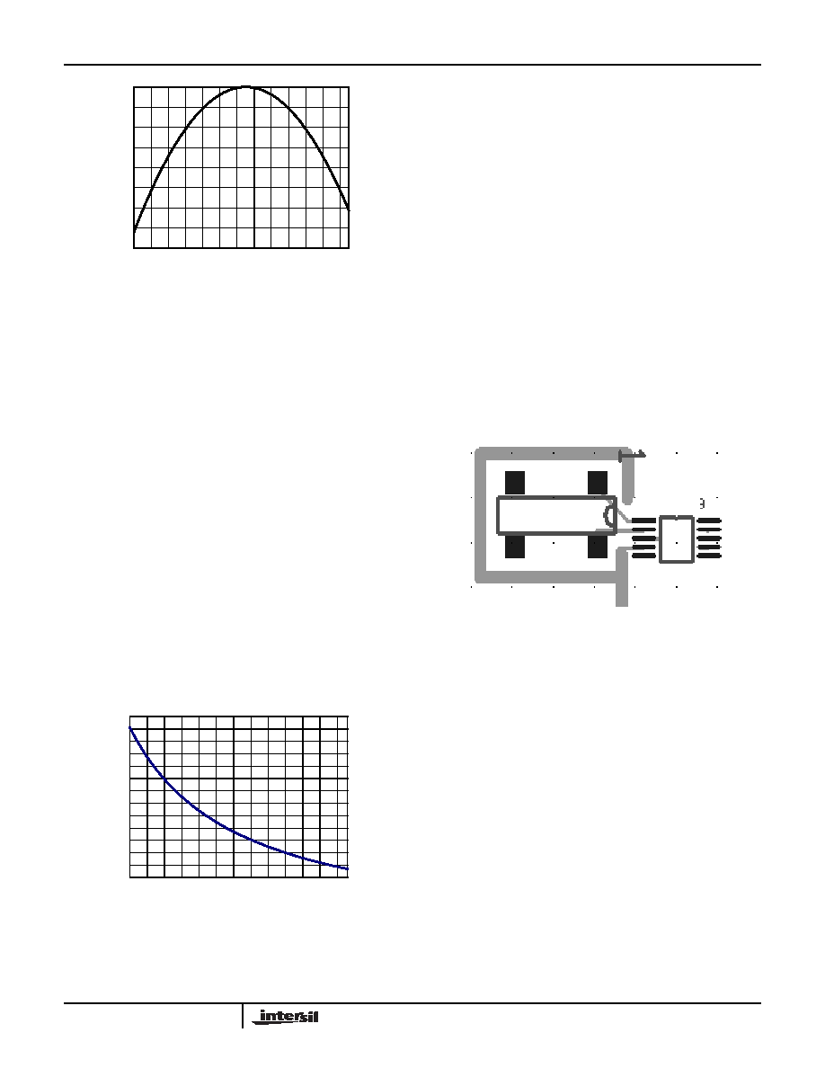
A sample curve of the ATR setting vs. Frequency Adjustment
for the ISL1221 and a typical RTC crystal is given in
Figure 21. This curve may vary with different crystals, so it is
good practice to evaluate a given crystal in an ISL1221
circuit before establishing the adjustment values.
This curve is then used to figure what ATR and DTR settings
are used for compensation. The results would be placed in a
lookup table for the microcontroller to access.
Layout Considerations
The crystal input at X1 has a very high impedance, and
oscillator circuits operating at low frequencies such as
32.768kHz are known to pick up noise very easily if layout
precautions are not followed. Most instances of erratic clocking
or large accuracy errors can be traced to the susceptibility of
the oscillator circuit to interference from adjacent high speed
clock or data lines. Careful layout of the RTC circuit will avoid
noise pickup and insure accurate clocking.
Figure 22 shows a suggested layout for the ISL1221 device
using a surface mount crystal. Two main precautions should
be followed:
1. Do not run the serial bus lines or any high speed logic lines
in the vicinity of the crystal. These logic level lines can
induce noise in the oscillator circuit to cause misclocking.
2. Add a ground trace around the crystal with one end
terminated at the chip ground. This will provide termination
for emitted noise in the vicinity of the RTC device.
In addition, it is a good idea to avoid a ground plane under
the X1 and X2 pins and the crystal, as this will affect the load
capacitance and therefore the oscillator accuracy of the
circuit. If the FOUT pin is used as a clock, it should be routed
away from the RTC device as well. The traces for the VBAT
and VDD pins can be treated as a ground, and should be
routed around the crystal.
Super Capacitor Backup
The ISL1221 device provides a VBAT pin which is used for a
battery backup input. A Super Capacitor can be used as an
alternative to a battery in cases where shorter backup times
are required. Since the battery backup supply current
required by the ISL1221 is extremely low, it is possible to get
months of backup operation using a Super Capacitor.
Typical capacitor values are a few F to 1 Farad or more
depending on the application.
If backup is only needed for a few minutes, then a small
inexpensive electrolytic capacitor can be used. For extended
periods, a low leakage, high capacity Super Capacitor is the
TEMPERATURE (°C)
-160.0
-140.0
-120.0
-100.0
-80.0
-60.0
-40.0
-20.0
0.0
-40 -30 -20 -10 0 1020 30 40 50607080
PPM
FIGURE 20. RTC CRYSTAL TEMPERATURE DRIFT
-40.0
-30.0
-20.0
-10.0
0.0
10.0
20.0
30.0
40.0
50.0
60.0
70.0
80.0
90.0
0
5 10 15 20 25 30 35 40 45 50 55 60
ATR SETTING
PP
M
ADJUS
T
M
E
N
T
FIGURE 21. ATR SETTING vs OSCILLATOR FREQUENCY
ADJUSTMENT
FIGURE 22. SUGGESTED LAYOUT FOR ISL1221 AND
CRYSTAL
ISL1221
ISL1221
相关PDF资料 |
PDF描述 |
|---|---|
| VE-J1D-MZ | CONVERTER MOD DC/DC 85V 25W |
| VI-JNZ-EY-F4 | CONVERTER MOD DC/DC 2V 20W |
| VE-J1B-MZ | CONVERTER MOD DC/DC 95V 25W |
| VE-J14-MZ | CONVERTER MOD DC/DC 48V 25W |
| VI-JNZ-EY-F3 | CONVERTER MOD DC/DC 2V 20W |
相关代理商/技术参数 |
参数描述 |
|---|---|
| ISL14010 | 制造商:INTERSIL 制造商全称:Intersil Corporation 功能描述:Low Jitter Clock Generators for Set-Top Box |
| ISL14010IRZ | 功能描述:时钟合成器/抖动清除器 REAL TIME CLKRTC 16LD 3X3 RoHS:否 制造商:Skyworks Solutions, Inc. 输出端数量: 输出电平: 最大输出频率: 输入电平: 最大输入频率:6.1 GHz 电源电压-最大:3.3 V 电源电压-最小:2.7 V 封装 / 箱体:TSSOP-28 封装:Reel |
| ISL14010IRZ-T | 功能描述:实时时钟 REAL TIME CLKRTC 16LD 3X3 RoHS:否 制造商:Microchip Technology 功能:Clock, Calendar. Alarm RTC 总线接口:I2C 日期格式:DW:DM:M:Y 时间格式:HH:MM:SS RTC 存储容量:64 B 电源电压-最大:5.5 V 电源电压-最小:1.8 V 最大工作温度:+ 85 C 最小工作温度: 安装风格:Through Hole 封装 / 箱体:PDIP-8 封装:Tube |
| ISL14011 | 制造商:INTERSIL 制造商全称:Intersil Corporation 功能描述:Low Jitter Clock Generators for Set-Top Box |
| ISL14011IRZ | 功能描述:时钟合成器/抖动清除器 REAL TIME CLKRTC 16LD 3X3 RoHS:否 制造商:Skyworks Solutions, Inc. 输出端数量: 输出电平: 最大输出频率: 输入电平: 最大输入频率:6.1 GHz 电源电压-最大:3.3 V 电源电压-最小:2.7 V 封装 / 箱体:TSSOP-28 封装:Reel |
发布紧急采购,3分钟左右您将得到回复。