参数资料
| 型号: | ISL32174EIVZ-T |
| 厂商: | Intersil |
| 文件页数: | 4/20页 |
| 文件大小: | 0K |
| 描述: | IC XMITTER ESD RS422 LP 16-TSSOP |
| 标准包装: | 2,500 |
| 类型: | 发射器 |
| 驱动器/接收器数: | 4/0 |
| 规程: | RS422 |
| 电源电压: | 3 V ~ 5.5 V |
| 安装类型: | 表面贴装 |
| 封装/外壳: | 16-TSSOP(0.173",4.40mm 宽) |
| 供应商设备封装: | 16-TSSOP |
| 包装: | 带卷 (TR) |
12
FN6824.1
March 13, 2013
discharge. The result is a more repeatable and predictable
test, but equipment limits prevent testing devices at voltages
higher than ±9kV. Devices in this family survive ±9kV contact
discharges on the RS-422 pins.
Data Rate, Cables, and Terminations
RS-422 is intended for network lengths up to 4000’, but the
maximum system data rate decreases as the transmission
length increases. Devices operating at 32Mbps handle
lengths up to 328’ (100m) in 5V systems, and lengths up to
460kbps versions can operate at full data rates with lengths
of thousands of feet. Note that system jitter requirements
may limit a network to shorter distances.
Twisted pair is the cable of choice for RS-422 networks.
Twisted pair cables tend to pick up noise and other
electromagnetically induced voltages as common mode
signals, which are effectively rejected by the differential
receivers in RS-422 ICs.
Proper termination is imperative, when using the 10Mbps or
32Mbps devices, to minimize reflections. Short networks
using the 460kbps versions need not be terminated, but,
terminations are recommended unless power dissipation is
an overriding concern.
In point-to-point, or point-to-multipoint (multiple receivers on
bus) networks, the main cable should be terminated in its
characteristic impedance (typically 120
Ω) at the end farthest
from the driver. In multi-receiver applications, stubs
connecting receivers to the main cable should be kept as
short as possible.
Built-In Driver Overload Protection
The driver output stages incorporate short circuit current
limiting circuitry which ensures that the output current never
exceeds the RS-422 specification. A novel design sets the
short circuit current limit depending on the VCC value, so
unlike some competing devices, the VCC = 5V short circuit
current is only slightly higher than the corresponding
In the event of a major short circuit condition, devices also
include a thermal shutdown feature that disables the drivers
whenever the die temperature becomes excessive. This
eliminates the power dissipation, allowing the die to cool. The
drivers automatically re-enable after the die temperature
drops about 20°. If the fault persists, the thermal
shutdown/re-enable cycle repeats until the fault is cleared.
High Temperature Operation
With TA = +125°C and VCC = 5.5V, four 100Ω differentially
terminated drivers in the TSSOP package put the IC at the
edge of its maximum allowed junction temperature. Using
larger termination resistors, a lower maximum supply
voltage, or one of the packages with a lower thermal
resistance (
θ
JA) provides more safety margin. When
designing for +125°C operation, be sure to measure the
application’s switching current, and include this in the
thermal calculations.
Low Power Shutdown Mode (ISL32179E Only)
These BiCMOS transmitters all use a fraction of the power
required by their bipolar counterparts, but the QFN version
includes a shutdown feature that reduces the already low
quiescent ICC by 90%. The ISL32179E enters shutdown
(SHDN) whenever the SHDNEN pin is high and all four
drivers are disabled (see “Pin Descriptions” on page 4). Note
that the enable times from SHDN are longer than the enable
times when the IC isn’t in SHDN.
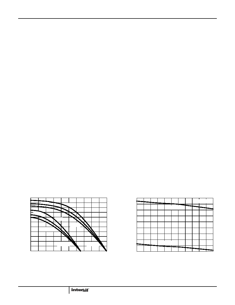
Typical Performance Curves VCC = VL = 3.3V or 5V, TA = +25°C; Unless Otherwise Specified. VL notes apply to the ISL32179E
only.
FIGURE 7. DRIVER OUTPUT CURRENT vs DIFFERENTIAL
OUTPUT VOLTAGE
FIGURE 8. DRIVER DIFFERENTIAL OUTPUT VOLTAGE vs
TEMPERATURE
DIFFERENTIAL OUTPUT VOLTAGE (V)
DRIVER
OUTPUT
CUR
RE
NT
(mA)
00.5
1.0
1.5
3.0
2.5
4.0
5.0
0
10
20
30
40
50
60
70
80
90
100
110
+25°C
+85°C
+125°C
+25°C
+125°C
+85°C
VCC = 3.3V
VCC = 5V
2.0
3.5
4.5
TEMPERATURE (°C)
DIFFERE
N
T
IAL
OUT
P
UT
VOL
TA
G
E
(V)
2.5
2.7
2.9
3.1
3.3
3.5
3.7
3.9
4.1
4.3
-40
-25
-10
5
20
35
50
65
80
95
110 125
RDIFF = 100Ω
VCC = 3.3V
VCC = 5V
ISL32172E, ISL32272E, ISL32372E, ISL32174E, ISL32274E, ISL32374E, ISL32179E
相关PDF资料 |
PDF描述 |
|---|---|
| MS27474E16F35PD | CONN RCPT 55POS JAM NUT W/PINS |
| V48B24M250BG | CONVERTER MOD DC/DC 24V 250W |
| PT02A-22-21P | CONN RCPT 21 POS BOX MNT W/PINS |
| V48B15M250BL3 | CONVERTER MOD DC/DC 15V 250W |
| MS27468E19F66P | CONN RCPT 66POS JAM NUT W/PINS |
相关代理商/技术参数 |
参数描述 |
|---|---|
| ISL32175E | 制造商:INTERSIL 制造商全称:Intersil Corporation 功能描述:QUAD, ±16.5kV ESD Protected, 3.0V to 5.5V, RS-485/RS-422 Receivers |
| ISL32175EFBZ | 功能描述:IC RCVR RS485/422 QD ESD 16SOIC RoHS:是 类别:集成电路 (IC) >> 接口 - 驱动器,接收器,收发器 系列:- 产品培训模块:Lead (SnPb) Finish for COTS Obsolescence Mitigation Program 标准包装:2,500 系列:- 类型:发射器 驱动器/接收器数:4/0 规程:RS422,RS485 电源电压:4.75 V ~ 5.25 V 安装类型:表面贴装 封装/外壳:16-SOIC(0.154",3.90mm 宽) 供应商设备封装:16-SOIC 包装:带卷 (TR) |
| ISL32175EFBZ-T | 功能描述:IC RCVR RS485/422 QD ESD 16SOIC RoHS:是 类别:集成电路 (IC) >> 接口 - 驱动器,接收器,收发器 系列:- 产品培训模块:Lead (SnPb) Finish for COTS Obsolescence Mitigation Program 标准包装:2,500 系列:- 类型:发射器 驱动器/接收器数:4/0 规程:RS422,RS485 电源电压:4.75 V ~ 5.25 V 安装类型:表面贴装 封装/外壳:16-SOIC(0.154",3.90mm 宽) 供应商设备封装:16-SOIC 包装:带卷 (TR) |
| ISL32175EFVZ | 功能描述:IC RCVR RS485/422 QD ESD 16TSSOP RoHS:是 类别:集成电路 (IC) >> 接口 - 驱动器,接收器,收发器 系列:- 产品培训模块:Lead (SnPb) Finish for COTS Obsolescence Mitigation Program 标准包装:2,500 系列:- 类型:发射器 驱动器/接收器数:4/0 规程:RS422,RS485 电源电压:4.75 V ~ 5.25 V 安装类型:表面贴装 封装/外壳:16-SOIC(0.154",3.90mm 宽) 供应商设备封装:16-SOIC 包装:带卷 (TR) |
| ISL32175EFVZ-T | 功能描述:IC RCVR RS485/422 QD ESD 16TSSOP RoHS:是 类别:集成电路 (IC) >> 接口 - 驱动器,接收器,收发器 系列:- 产品培训模块:Lead (SnPb) Finish for COTS Obsolescence Mitigation Program 标准包装:2,500 系列:- 类型:发射器 驱动器/接收器数:4/0 规程:RS422,RS485 电源电压:4.75 V ~ 5.25 V 安装类型:表面贴装 封装/外壳:16-SOIC(0.154",3.90mm 宽) 供应商设备封装:16-SOIC 包装:带卷 (TR) |
发布紧急采购,3分钟左右您将得到回复。