- 您现在的位置:买卖IC网 > PDF目录11791 > ISL54100CQZ (Intersil)IC REGENERATOR TMDS 4:1 128-MQFP PDF资料下载
参数资料
| 型号: | ISL54100CQZ |
| 厂商: | Intersil |
| 文件页数: | 6/21页 |
| 文件大小: | 0K |
| 描述: | IC REGENERATOR TMDS 4:1 128-MQFP |
| 标准包装: | 66 |
| 应用: | 多媒体显示器,测试设备 |
| 接口: | I²C |
| 电源电压: | 3 V ~ 3.6 V |
| 封装/外壳: | 128-BFQFP |
| 供应商设备封装: | 128-MQFP(14x20) |
| 包装: | 托盘 |
| 安装类型: | 表面贴装 |
| 产品目录页面: | 1244 (CN2011-ZH PDF) |
14
FN6275.5
June 4, 2008
Power-down
The chip can be placed in a Power-down mode when not in
use to conserve power. Setting the Power-down bit (register
0x02 bit 5) to a 1 or pulling the PD input pin high places the
chip in a minimal power consumption mode, turning off all
TMDS outputs and disconnecting all TMDS inputs. Serial I/O
stays operational in PD mode. Note that the PD pin must be
low during power-on in order to initialize the I2C interface.
Note: When exiting Power-down, a termination resistor
Recalibration cycle must be run to re-trim the termination
resistors (see register 0x03[7]).
Power Dissipation and Supply Current
Due to the large number of TMDS inputs and outputs, a
significant amount of current flows into and out of the
SL5410x. This makes calculating the total power dissipation
of the ISL5410x slightly more complicated than simply
multiplying the supply current by the supply voltage.
The supply current measurement includes the current
flowing through all the active TMDS termination resistors.
This current is supplied by the ISL54100's VD supplies, but
only 15% of it (0.5V*10mA per TMDS pair) is dissipated as
power inside the ISL54100. The majority of the power (2.8V
* 10mA per active TMDS pair) is dissipated in the TMDS
transmitter driving the ISL54100. Likewise, the ISL54100
dissipates 85% of the power generated by the current from
the external receiver attached to the ISL54100's Tx pins.
Any worst-case on-chip power dissipation calculation needs
to account for this.
Inter-Pair (Channel-to-Channel) Skew
The read pointers for Channel 0, 1, and 2 of the FIFO that
follows the CDR all have the same clock, so all 3 channels
transition within a few picoseconds of each other - there is
essentially no skew between the transitions of the three
channels.
However the FIFO read pointers may be positioned up to 2
bits apart relative to each other, introducing a random, fixed
channel-to-channel skew of skew of 1 or (much less
frequently) 2 bits. The random skew is introduced whenever
there is a discontinuity in the input signal (typically a video
mode change or a new mux channel selection). After the
CDRs and PLL lock, the skew is fixed until the next
discontinuity. This adds up to 2 bits of skew in addition to any
incoming skew, as shown in the following examples.
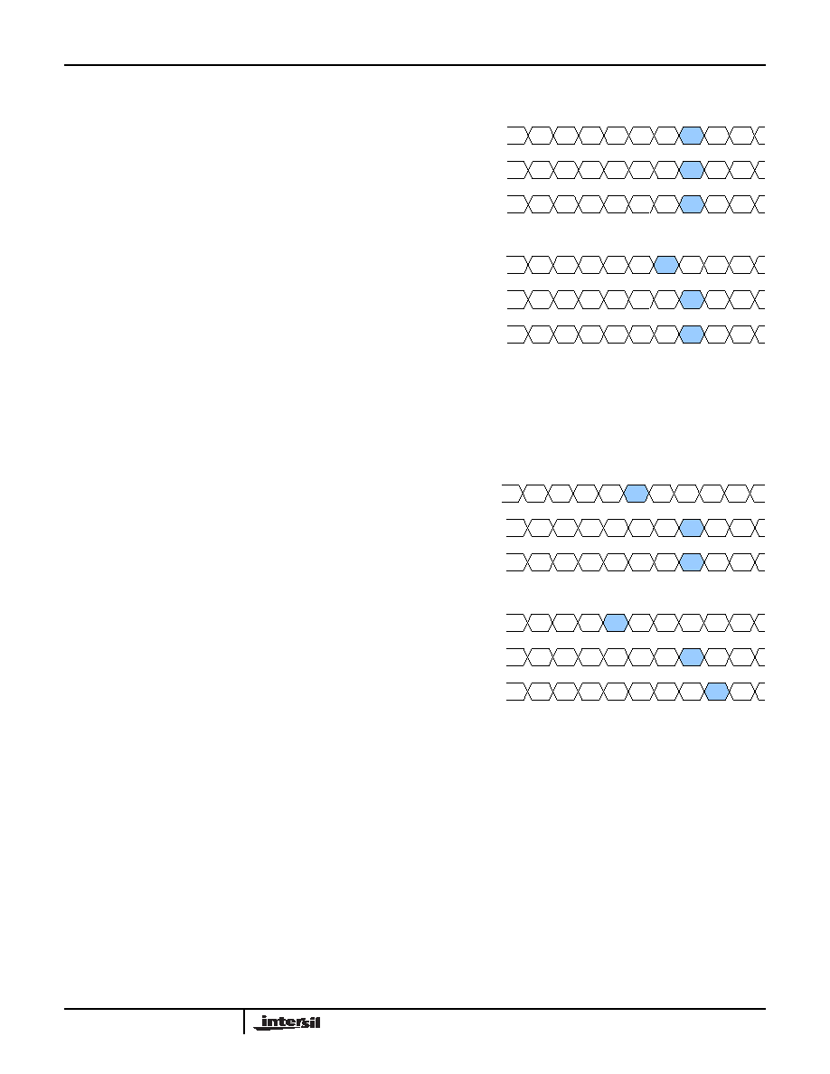
Figure 2 shows an input (the top three signals) with
essentially no skew. After the ISL5410x locks on to the
signal, there may be 1 bit of skew on the output, as shown in
When there is pre-existing skew on the input, the ISL5410x
can add up to 2 bits to the channel-to-channel skew. In the
example in Figure 3, the incoming red channel has 2.3 bits of
skew relative to the incoming green and blue. The FIFO’s
quantization (worst case) increases the total skew to 4.0 bits.
While increasing skew is not desirable, DVI and HDMI
receivers are required to have a minimum of 6 bits of inter-
pair skew tolerance, so the addition of 2 bits of skew is only a
problem with the most pathological cables and transmitters.
It does, however, limit the number of ISL5410xs that can be
put in series (although statistically it is unlikely that all the
skews would line up in a worst-case configuration).
FIGURE 2. MAXIMUM ADDITIONAL INTERCHANNEL SKEW
FOR INPUTS WITH NO OR LITTLE SKEW
Bit 4
Bit 5
Bit 6
Bit 7
Bit 0
Bit 1
Bit 2
Bit 3
B
Bit 8
Bit 9
Bit 4
Bit 5
Bit 6
Bit 7
Bit 0
Bit 1
Bit 2
Bit 3
B
Bit 8
Bit 9
Bit 4
Bit 5
Bit 6
Bit 7
Bit 0
Bit 1
Bit 2
Bit 3
B
Bit 8
Bit 9
Bit 4
Bit 5
Bit 6
Bit 0
Bit 1
Bit 2
Bit 3
B
Bit 7
Bit 8
Bit 9
Bit 4
Bit 5
Bit 6
Bit 7
Bit 0
Bit 1
Bit 2
Bit 3
B
Bit 8
Bit 9
Bit 4
Bit 5
Bit 6
Bit 7
Bit 0
Bit 1
Bit 2
Bit 3
B
Bit 8
Bit 9
INPUT SKEW
(none, in this
example)
OUTPUT SKEW
(1 bit – 615ps at
162.5Mpixels/s)
Bit 4
Bit 5
Bit 0
Bit 1
Bit 2
Bit 3
Bit 7
Bit 8
Bit 9
Bit 4
Bit 5
Bit 6
Bit 7
Bit 0
Bit 1
Bit 2
Bit 3
B
Bit 8
Bit 9
Bit 4
Bit 5
Bit 6
Bit 7
Bit 0
Bit 1
Bit 2
Bit 3
B
Bit 8
Bit 9
Bit 4
Bit 0
Bit 1
Bit 2
Bit 3
Bit 6
Bit 7
Bit 8
Bit 9
Bit 4
Bit 5
Bit 6
Bit 7
Bit 0
Bit 1
Bit 2
Bit 3
B
Bit 8
Bit 9
Bit 4
Bit 5
Bit 6
Bit 7
Bit 0
Bit 1
Bit 2
Bit 3
B
Bit 9
INPUT SKEW
(2.3 bits/1.4ns
in this example)
OUTPUT SKEW
(4 bits/2.5ns at
162.5Mpixels/s)
Bit
Bit 6
B
Bit 5
Bit 8
FIGURE 3. MAXIMUM ADDITIONAL INTERCHANNEL SKEW
FOR INPUTS WITH MODERATE TO LARGE
SKEW
ISL54100, ISL54101, ISL54102
相关PDF资料 |
PDF描述 |
|---|---|
| ISL54102ACQZ | IC TMDS REGEN W/MUX 128-MQFP |
| ISL54102CQZ | IC TMDS REGEN W/MUX 128MQFP |
| IA186ES-PTQ100I-R-03 | IC MCU 8/16BIT 40MHZ 100TQFP |
| PI7C8152BMAE | IC PCI-PCI BRIDGE 2PORT 160-MQFP |
| DS80C310-MCG+ | IC MCU HI SPEED 25MHZ 40-DIP |
相关代理商/技术参数 |
参数描述 |
|---|---|
| ISL54100CQZ-EVAL | 制造商:Intersil Corporation 功能描述:ISL54100CQZ-EVAL EVALUATION BOARD - Bulk |
| ISL54100CQZ-EVALZ | 制造商:Intersil Corporation 功能描述:EVAL BD FOR ISL54100 TMDS REGENERATORS W/ MLTPLXRS - Bulk |
| ISL54100-EVM | 制造商:Intersil Corporation 功能描述:An Evaluation Board of Manual, automatic and infrared remote control,4:1 HDMI interface, and a CD of development files 制造商:Intersil Corporation 功能描述:An Evaluation Board of Manual, automatic and infrared remote control4:1 HDMI interface, and a CD of development files |
| ISL54100HDMI-EVALZ | 制造商:Intersil Corporation 功能描述:ISL54100HDMI EVALUATION BOARD, ROHS, 4HDMI IN, 1 HDMI OUT - Bulk |
| ISL54101ACQZ | 功能描述:IC TMDS REGEN W/MUX 128-MQFP RoHS:是 类别:集成电路 (IC) >> 接口 - 专用 系列:- 标准包装:3,000 系列:- 应用:PDA,便携式音频/视频,智能电话 接口:I²C,2 线串口 电源电压:1.65 V ~ 3.6 V 封装/外壳:24-WQFN 裸露焊盘 供应商设备封装:24-QFN 裸露焊盘(4x4) 包装:带卷 (TR) 安装类型:表面贴装 产品目录页面:1015 (CN2011-ZH PDF) 其它名称:296-25223-2 |
发布紧急采购,3分钟左右您将得到回复。