- 您现在的位置:买卖IC网 > PDF目录383135 > ISL5585FCR (INTERSIL CORP) 3.3V Ringing SLIC Family for Voice Over Broadband VOB PDF资料下载
参数资料
| 型号: | ISL5585FCR |
| 厂商: | INTERSIL CORP |
| 元件分类: | 模拟传输电路 |
| 英文描述: | 3.3V Ringing SLIC Family for Voice Over Broadband VOB |
| 中文描述: | TELECOM-SLIC, PQCC32 |
| 封装: | 7 X 7 MM, PLASTIC, MO-220VKKC, QFN-32 |
| 文件页数: | 14/22页 |
| 文件大小: | 425K |
| 代理商: | ISL5585FCR |
14
Low Power Standby
Overview
The low power standby mode (LPS, 000) should be used
during idle line conditions. The device is designed to operate
from the high battery during this mode. Most of the internal
circuitry is powered down, resulting in low power dissipation.
If the 2-wire (tip/ring) DC voltage requirements are not
critical during idle line conditions, the device may be
operated from the low battery. Operation from the low
battery will decrease the standby power dissipation.
2-Wire Interface
During LPS, the 2-wire interface is maintained with internal
switches and voltage references. The Tip and Ring
amplifiers are turned off to conserve power. The device will
provide MTU compliance, loop current and loop supervision.
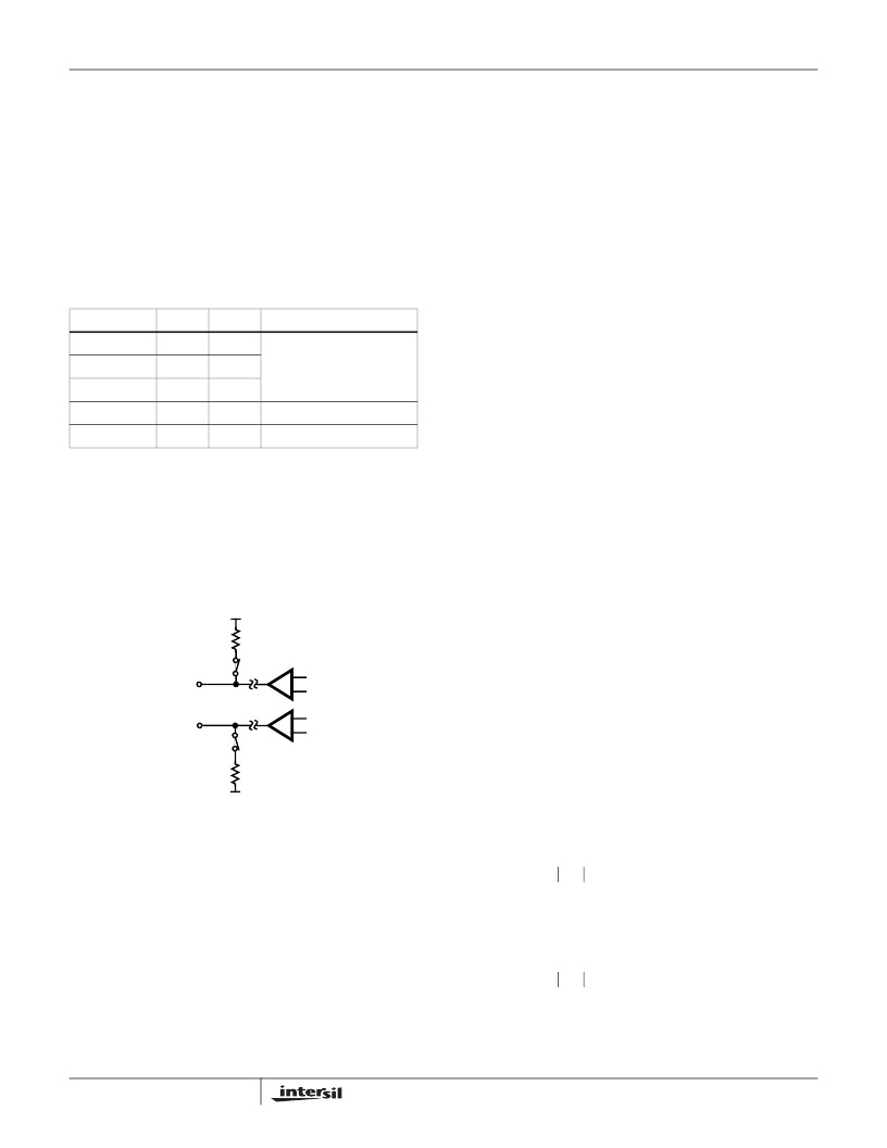
Figure 8 represents the internal circuitry providing the 2-wire
interface during low power standby.
MTU Compliance
Maintenance Termination Unit or MTU compliance places
DC voltage requirements on the 2-wire terminals during idle
line conditions. The minimum idle voltage is 42.75V. The
high side of the MTU range is 56V. The voltage is expressed
as the difference between Tip and Ring.
The Tip voltage is held near ground through a 600
resistor
and switch. The Ring voltage is limited to a maximum of
-56V (by MTU REF) when operating from either the high or
low battery. A switch and 600
resistor connect the MTU
reference to the Ring terminal. When the high battery
voltage exceeds the MTU reference of -56V, the Ring
terminal will be clamped by the internal reference (typically -
54V). The same Ring relationships apply when operating
from the low battery voltage. For high battery voltages (V
BH
)
less than or equal to the internal MTU reference threshold:
Loop Current
During LPS, the device will provide current to a load. The
current path is through resistors and switches, and is a
function of the off hook loop resistance (R
LOOP
). This
includes the off hook phone resistance and copper loop
resistance. The current available during LPS is determined
by Equation 44.
Internal current limiting of the standby switches will limit the
maximum current to approximately 20mA.
Another loop current related parameter is longitudinal
current capability. The longitudinal current capability is
reduced. The reduction in longitudinal current capability is a
result of turning off the Tip and Ring amplifiers.
On Hook Power Dissipation
The on hook power dissipation of the device during LPS is
determined by the operating voltages and quiescent currents
and is calculated using Equation 45.
The quiescent current terms are specified in the electrical
tables for each operating mode. Load power dissipation is
not a factor since this is an on hook mode. Some
applications may specify a standby current. The standby
current may be a charging current required for modern
telephone electronics.
Standby Current Power Dissipation
Any standby line current, I
SLC
, introduces an additional
power dissipation term P
SLC
. Equation 46 illustrates the
power contribution is zero when the standby line current is
zero.
If the battery voltage is less than -54V (the MTU clamp is
off), the standby line current power contribution reduces to
Equation 47.
TABLE 1. DEVICE INTERFACES DURING LPS
INTERFACE
ON
OFF
NOTES
Receive
x
AC transmission, impedance
matching and ringing are
disabled during this mode.
Ringing
x
Transmit
x
2-Wire
x
Amplifiers disabled.
Loop Detect
x
Switch hook or ground key.
FIGURE 8. LPS 2-WIRE INTERFACE CIRCUIT DIAGRAM
TIP AMP
RING AMP
TIP
RING
MTU REF
GND
600
600
V
RING
V
BH
5
+
=
(EQ. 43)
I
LOOP
1
–
54
–
(
)
–
(
)
600
600
R
LOOP
+
+
(
)
=
(EQ. 44)
P
LPS
V
BH
I
BHQ
×
V
BL
I
BLQ
×
V
CC
I
CCQ
×
+
+
=
(EQ. 45)
P
SLC
I
SLC
V
BH
54
–
1
I
SLC
x1200
+
+
(
)
×
=
(EQ. 46)
P
SLC
I
SLC
V
BH
1
I
SLC
x1200
+
+
(
)
×
=
(EQ. 47)
ISL5585
相关PDF资料 |
PDF描述 |
|---|---|
| ISL5586BIM | Low Power Ringing SLIC for Home Gateways |
| ISL5586FCM | Low Power Ringing SLIC for Home Gateways |
| ISL5586CIM | Low Power Ringing SLIC for Home Gateways |
| ISL5586DIM | Low Power Ringing SLIC for Home Gateways |
| ISL56292IN | Dual 8-bit, +3.3V, 130/210MSPS, CommLink TM High Speed D/A Converter |
相关代理商/技术参数 |
参数描述 |
|---|---|
| ISL5585FCR-TK | 功能描述:IC SLIC RINGING 3.3V VOB 32-QFN RoHS:否 类别:集成电路 (IC) >> 接口 - 电信 系列:- 产品培训模块:Lead (SnPb) Finish for COTS 产品变化通告:Product Discontinuation 06/Feb/2012 标准包装:750 系列:* |
| ISL5585FCRZ | 制造商:Intersil Corporation 功能描述: 制造商:Intersil Corporation 功能描述:Telecom Line Management ICs RINGING SLIC W/3 3V VCC 75V/53DB |
| ISL5585FCRZ-T | 制造商:Intersil Corporation 功能描述:PB-FREE RINGING SLIC W/3.3V VCC, 75V/53DB T&R - Tape and Reel |
| ISL5585FCRZ-TK | 功能描述:IC SLIC RINGING 3.3V VOB 32-QFN RoHS:是 类别:集成电路 (IC) >> 接口 - 电信 系列:- 产品培训模块:Lead (SnPb) Finish for COTS 产品变化通告:Product Discontinuation 06/Feb/2012 标准包装:750 系列:* |
| ISL5585GCM | 制造商:Rochester Electronics LLC 功能描述: 制造商:Intersil Corporation 功能描述: |
发布紧急采购,3分钟左右您将得到回复。