- 您现在的位置:买卖IC网 > PDF目录10837 > ISL59442IB (Intersil)IC CROSSPOINT SW 1GHZ 4X1 14SOIC PDF资料下载
参数资料
| 型号: | ISL59442IB |
| 厂商: | Intersil |
| 文件页数: | 11/11页 |
| 文件大小: | 0K |
| 描述: | IC CROSSPOINT SW 1GHZ 4X1 14SOIC |
| 标准包装: | 55 |
| 应用: | 4:1 多路复用器-放大器 |
| 电路数: | 1 |
| -3db带宽: | 1GHz |
| 转换速率: | 1452 V/µs |
| 电流 - 电源: | 18mA |
| 电流 - 输出 / 通道: | 180mA |
| 电压 - 电源,单路/双路(±): | ±4.5 V ~ 5.5 V |
| 安装类型: | 表面贴装 |
| 封装/外壳: | 14-SOIC(0.154",3.90mm 宽) |
| 供应商设备封装: | 14-SOICN |
| 包装: | 管件 |
9
FN7452.4
January 5, 2007
Application Information
General
The ISL59442 is a 4:1 mux that is ideal as a matrix element in
high performance switchers and routers. The ISL59442 is
optimized to drive a 2pF in parallel with a 500
Ω load. The
capacitance can be split between the PCB capacitance an and
external load capacitance. Their low input capacitance and high
input resistance provide excellent 50
Ω or 75Ω terminations.
Capacitance at the Output
The output amplifier is optimized for capacitance to ground
(CL) directly on the output pin. Increased capacitance
causes higher peaking with an increase in bandwidth. The
optimum range for most applications is ~1.0pF to ~6pF. The
optimum value can be achieved through a combination of
PC board trace capacitance (CT) and an external capacitor
(COUT). A good method to maintain control over the output
pin capacitance is to minimize the trace length (CT) to the
next component, and include a discrete surface mount
capacitor (COUT) directly at the output pin.
For large signal applications where overshoot is important
the circuit in Figure 24B should be used. The series resistor
(RS) and capacitor (CL) form a low pass network that limits
system bandwidth and reduces overshoot. The component
values shown result in a typical pulse response shown in
Figure 20.
Ground Connections
For the best isolation and crosstalk rejection, the GND pin
and NIC pins must connect to the GND plane. The NIC pins
are placed on both sides of the input pins. These pins are
not internally connected to the die. It is recommended this
pin be tied to ground to minimize crosstalk.
Control Signals
S0, S1, HIZ - These pins are, TTL/CMOS compatible control
inputs. The S0, S1 pins select which one of the inputs
connect to the output. The HIZ pin is used to three-state the
output amplifiers. For control signal rise and fall times less
than 10nsec the use of termination resistors close to the part
will minimize transients coupled to the output.
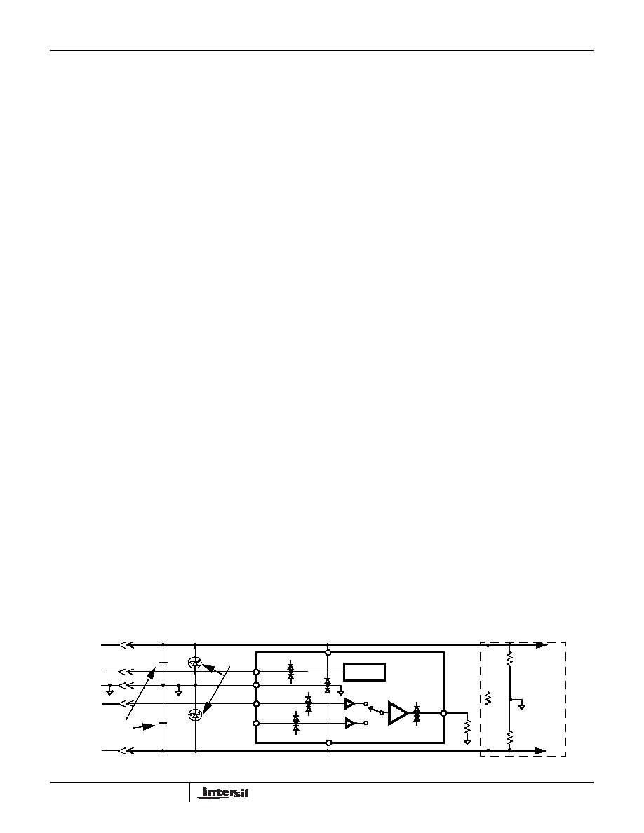
Power-Up Considerations
The ESD protection circuits use internal diodes from all pins the
V+ and V- supplies. In addition, a dV/dT- triggered clamp is
connected between the V+ and V- pins, as shown in the
Equivalent Circuits 1 through 4 section of the Pin Description
table. The dV/dT triggered clamp imposes a maximum supply
turn-on slew rate of 1V/s. Damaging currents can flow for
power supply rates-of-rise in excess of 1V/s, such as during
hot plugging. Under these conditions, additional methods
should be employed to ensure the rate of rise is not exceeded.
Consideration must be given to the order in which power is
applied to the V+ and V- pins, as well as analog and logic
input pins. Schottky diodes (Motorola MBR0550T or
equivalent) connected from V+ to ground and V- to ground
(Figure 25) will shunt damaging currents away from the
internal V+ and V- ESD diodes in the event that the V+
supply is applied to the device before the V- supply.
If positive voltages are applied to the logic or analog video
input pins before V+ is applied, current will flow through the
internal ESD diodes to the V+ pin. The presence of large
decoupling capacitors and the loading effect of other circuits
connected to V+, can result in damaging currents through
the ESD diodes and other active circuits within the device.
Therefore, adequate current limiting on the digital and
analog inputs is needed to prevent damage during the time
the voltages on these inputs are more positive than V+.
HIZ State
An internal pull-down resistor connected to the HIZ pin ensures
the device will be active with no connection to the HIZ pin. The
HIZ state is established within approximately 30ns by placing a
logic high (>2V) on the HIZ pin. If the HIZ state is selected, the
output is a high impedance 1.4M
Ω. Use this state to control the
logic when more than one mux shares a common output.
In the HIZ state the output is three-stated, and maintains its
high Z even in the presence of high slew rates. The supply
current during this state is basically the same as the active
state.
Limiting the Output Current
No output short circuit current limit exists on these parts. All
applications need to limit the output current to less than 50mA.
Adequate thermal heat sinking of the parts is also required.
V+
V-
V+
V-
V+
V-
LOGIC
CONTROL
GND
IN0
IN1
S0
OUT
EXTERNAL
CIRCUITS
SCHOTTKY
PROTECTION
V+
V-
POWER
GND
SIGNAL
LOGIC
V+ SUPPLY
V- SUPPLY
DE-COUPLING
CAPS
FIGURE 25. SCHOTTKY PROTECTION CIRCUIT
ISL59442
相关PDF资料 |
PDF描述 |
|---|---|
| MX7226KP+T | IC DAC 8BIT W/AMP 20-PLCC |
| MAX5151ACEE+ | IC DAC 13BIT DUAL LP SER 16-QSOP |
| MAX5150ACEE+ | IC DAC 13BIT DUAL LP SER 16-QSOP |
| ISL59441IA-T13 | IC AMP MULTIPLEX 900MHZ 16-QSOP |
| MAX5153ACEE+ | IC DAC 13BIT DUAL LP SER 16-QSOP |
相关代理商/技术参数 |
参数描述 |
|---|---|
| ISL59442IB-T13 | 功能描述:IC CROSSPOINT SW 1GHZ 4X1 14SOIC RoHS:否 类别:集成电路 (IC) >> 线性 - 放大器 - 视频放大器和频缓冲器 系列:- 产品培训模块:Lead (SnPb) Finish for COTS Obsolescence Mitigation Program 标准包装:50 系列:- 应用:TFT-LCD 面板:VCOM 驱动器 输出类型:满摆幅 电路数:1 -3db带宽:35MHz 转换速率:40 V/µs 电流 - 电源:3.7mA 电流 - 输出 / 通道:1.3A 电压 - 电源,单路/双路(±):9 V ~ 20 V,±4.5 V ~ 10 V 安装类型:表面贴装 封装/外壳:8-TSSOP,8-MSOP(0.118",3.00mm 宽)裸露焊盘 供应商设备封装:8-uMax-EP 包装:管件 |
| ISL59442IB-T7 | 功能描述:IC CROSSPOINT SW 1GHZ 4X1 14SOIC RoHS:否 类别:集成电路 (IC) >> 线性 - 放大器 - 视频放大器和频缓冲器 系列:- 产品培训模块:Lead (SnPb) Finish for COTS Obsolescence Mitigation Program 标准包装:50 系列:- 应用:TFT-LCD 面板:VCOM 驱动器 输出类型:满摆幅 电路数:1 -3db带宽:35MHz 转换速率:40 V/µs 电流 - 电源:3.7mA 电流 - 输出 / 通道:1.3A 电压 - 电源,单路/双路(±):9 V ~ 20 V,±4.5 V ~ 10 V 安装类型:表面贴装 封装/外壳:8-TSSOP,8-MSOP(0.118",3.00mm 宽)裸露焊盘 供应商设备封装:8-uMax-EP 包装:管件 |
| ISL59442IBZ | 功能描述:IC CROSSPOINT SW 1GHZ 4X1 14SOIC RoHS:是 类别:集成电路 (IC) >> 线性 - 放大器 - 视频放大器和频缓冲器 系列:- 标准包装:1,000 系列:- 应用:驱动器 输出类型:差分 电路数:3 -3db带宽:350MHz 转换速率:1000 V/µs 电流 - 电源:14.5mA 电流 - 输出 / 通道:60mA 电压 - 电源,单路/双路(±):5 V ~ 12 V,±2.5 V ~ 6 V 安装类型:表面贴装 封装/外壳:20-VFQFN 裸露焊盘 供应商设备封装:20-QFN 裸露焊盘(4x4) 包装:带卷 (TR) |
| ISL59442IBZ-EVAL | 功能描述:EVAL BOARD FOR ISL59442 RoHS:否 类别:编程器,开发系统 >> 评估演示板和套件 系列:* 标准包装:1 系列:PSoC® 主要目的:电源管理,热管理 嵌入式:- 已用 IC / 零件:- 主要属性:- 次要属性:- 已供物品:板,CD,电源 |
| ISL59442IBZ-T13 | 功能描述:IC AMP MULTIPLEX 1GHZ 14SOIC RoHS:是 类别:集成电路 (IC) >> 线性 - 放大器 - 视频放大器和频缓冲器 系列:- 标准包装:1,000 系列:- 应用:驱动器 输出类型:差分 电路数:3 -3db带宽:350MHz 转换速率:1000 V/µs 电流 - 电源:14.5mA 电流 - 输出 / 通道:60mA 电压 - 电源,单路/双路(±):5 V ~ 12 V,±2.5 V ~ 6 V 安装类型:表面贴装 封装/外壳:20-VFQFN 裸露焊盘 供应商设备封装:20-QFN 裸露焊盘(4x4) 包装:带卷 (TR) |
发布紧急采购,3分钟左右您将得到回复。