参数资料
| 型号: | ISL59452IRZ-T7 |
| 厂商: | Intersil |
| 文件页数: | 5/15页 |
| 文件大小: | 0K |
| 描述: | IC AMP MUX TRIPLE 4:1 DC 32-QFN |
| 标准包装: | 1,000 |
| 应用: | 4:1 多路复用器-放大器 |
| 电路数: | 3 |
| -3db带宽: | 250MHz |
| 转换速率: | 980 V/µs |
| 电流 - 电源: | 45mA |
| 电流 - 输出 / 通道: | 125mA |
| 电压 - 电源,单路/双路(±): | 4.5 V ~ 5.5 V |
| 安装类型: | 表面贴装 |
| 封装/外壳: | 32-VFQFN 裸露焊盘 |
| 供应商设备封装: | 32-TQFN-EP(5x5) |
| 包装: | 带卷 (TR) |
13
FN6254.0
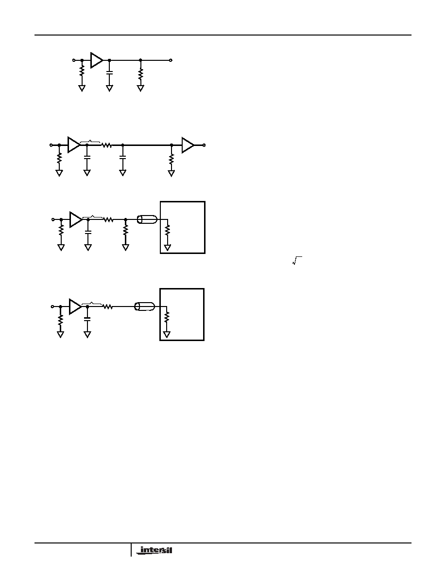
AC Test Circuits
testing AC performance at 150
Ω loads. Figure 32C
illustrates how to use the optimal 150
Ω load for a 50Ω cable.
Figure 32D illustrates the optimum output load for 50
Ω and
75
Ω cable-driving.
Application Information
General
The ISL59452 triple 4:1 video MUX features +5V single-supply
operation, high bandwidth and TTL/CMOS logic compatible
gain select (AV2) of x1 (0dB) or x2 (+6dB). The ISL59452 also
features buffered high impedance analog inputs and excellent
AC performance at output loads down to 150
Ω for video cable-
driving. The current feedback output amplifiers are stable
operating into capacitive loads.
AC Design Considerations
High speed current-feed amplifiers are sensitive to
capacitance at the inverting input and output terminals.
Capacitance at the output terminal increases gain peaking
and overshoot. The AC response of the ISL59452 is
optimized for a total output capacitance of 2.1pF with a load
of 150
Ω (Figure 32A). When PCB trace capacitance and
component capacitance exceed 2pF, overshoot becomes
strongly dependent on the input pulse amplitude and slew
rate. Increasing levels of output capacitance reduce stability,
resulting in increased overshoot and settling time.
PC board trace length (LCRIT) should be kept to a minimum
in order to minimize output capacitance. At 500MHz, trace
lengths approaching 1” begin exhibiting transmission line
behavior and may cause excessive ringing if controlled
impedance traces are not used. Figure 32B shows the
optimum inter-stage circuit when the total output trace length
is less than the critical length of the highest signal frequency.
As a general rule of thumb the trace lengths should be less
than one-tenth of the wavelength of the highest frequency
component in the signal. Equation 1 shows an approximate
way to calculate LCRIT in meters.
c = speed of light (3 x 10^8 m/s)
fMAX = maximum frequency component
εR = relative dielectric of board material (e.g. FR4 = 4.2)
For applications where inter-stage distances are long but
pulse response is not critical, capacitor CS can be added to
low values of RS to form a low-pass filter to dampen pulse
overshoot. This approach avoids the need for the large gain
correction required by the -6dB attenuation of the
back-loaded controlled impedance interconnect. Load
resistor RL is still required but can be 500Ω or greater,
resulting in a much smaller attenuation factor.
For applications where pulse response is critical and where
inter-stage distances exceed LCRIT, the circuit shown in
capacitance seen by the amplifier output to the trace
capacitance betweeen the output pin and the resistor.
Therefore, RS should be placed as close to the ISL59452
output pin as possible. For inter-stage distances much greater
should be used with controlled impedance PCB lines, with RS
and RL equal to the controlled impedance.
Control Signals
S0, S1, AV2, and HIZ are binary coded, TTL/CMOS
compatible control inputs. The S0, S1 pins select the inputs.
All three output amplifiers are switched simultaneously from
their respective inputs. When HIZ is pulled high, it puts the
outputs in a high-impedance state. For control signal rise and
FIGURE 32A. TEST CIRCUIT WITH OPTIMAL OUTPUT LOAD
FIGURE 32B. INTER-STAGE APPLICATION CIRCUIT
FIGURE 32C. 150
Ω TEST CIRCUIT WITH 50Ω LOAD
FIGURE 32D. BACKLOADED TEST CIRCUIT FOR 150
Ω VIDEO
CABLE APPLICATION
FIGURE 32. AC TEST CIRCUITS
ISL59452
*CL
50
Ω
VIN
RL
2.1pF
or
75
Ω
150
Ω
*CL Includes PCB trace capacitance
VOUT
x2
ISL59452
CS
50
Ω
VIN
RL
or
75
Ω
LCRIT
RS
CL
x2
ISL59452
RS
*CL
VIN
118
Ω
TEST
2.1pF
50
Ω,or
86.6
Ω
50
Ω
EQUIPMENT
75
Ω
*CL Includes PCB trace capacitance
LCRIT
x2
ISL59452
RS
*CL
VIN
50
Ω or 75Ω
TEST
2.1pF
50
Ω
or
75
Ω
EQUIPMENT
*CL Includes PCB trace capacitance
LCRIT
x2
50
Ω/75Ω
L
CRIT
c
10
f
MAX
ε
R
×
--------------------------------------------
≤
(EQ. 1)
ISL59452
相关PDF资料 |
PDF描述 |
|---|---|
| ISL59481IRZ | IC MUX AMP DUAL 500MHZ 48-QFN |
| ISL59482IRZ | IC MUX AMP DUAL 500MHZ 48-QFN |
| ISL59483IRZ | IC MUX AMP DUAL 500MHZ 48-QFN |
| ISL59605IRZ-T7A | IC VIDEO EQUALIZER 20-QFN |
| ISL59830AIAZ-T7 | IC VIDEO DRIVER TRUE SGL 16-QSOP |
相关代理商/技术参数 |
参数描述 |
|---|---|
| ISL59481 | 制造商:INTERSIL 制造商全称:Intersil Corporation 功能描述:Dual, 500MHz Triple, Multiplexing Amplifiers |
| ISL59481_07 | 制造商:INTERSIL 制造商全称:Intersil Corporation 功能描述:Dual, 500MHz Triple, Multiplexing Amplifiers |
| ISL59481EVAL1Z | 功能描述:EVAL BOARD 1 FOR ISL59481 RoHS:是 类别:编程器,开发系统 >> 评估演示板和套件 系列:* 标准包装:1 系列:PCI Express® (PCIe) 主要目的:接口,收发器,PCI Express 嵌入式:- 已用 IC / 零件:DS80PCI800 主要属性:- 次要属性:- 已供物品:板 |
| ISL59481IRZ | 功能描述:IC MUX AMP DUAL 500MHZ 48-QFN RoHS:是 类别:集成电路 (IC) >> 线性 - 放大器 - 视频放大器和频缓冲器 系列:- 标准包装:1,000 系列:- 应用:驱动器 输出类型:差分 电路数:3 -3db带宽:350MHz 转换速率:1000 V/µs 电流 - 电源:14.5mA 电流 - 输出 / 通道:60mA 电压 - 电源,单路/双路(±):5 V ~ 12 V,±2.5 V ~ 6 V 安装类型:表面贴装 封装/外壳:20-VFQFN 裸露焊盘 供应商设备封装:20-QFN 裸露焊盘(4x4) 包装:带卷 (TR) |
| ISL59481IRZ-T13 | 功能描述:IC MUX AMP DUAL 500MHZ 48-QFN RoHS:是 类别:集成电路 (IC) >> 线性 - 放大器 - 视频放大器和频缓冲器 系列:- 标准包装:1,000 系列:- 应用:驱动器 输出类型:差分 电路数:3 -3db带宽:350MHz 转换速率:1000 V/µs 电流 - 电源:14.5mA 电流 - 输出 / 通道:60mA 电压 - 电源,单路/双路(±):5 V ~ 12 V,±2.5 V ~ 6 V 安装类型:表面贴装 封装/外壳:20-VFQFN 裸露焊盘 供应商设备封装:20-QFN 裸露焊盘(4x4) 包装:带卷 (TR) |
发布紧急采购,3分钟左右您将得到回复。