参数资料
| 型号: | ISL59483IRZ |
| 厂商: | Intersil |
| 文件页数: | 7/17页 |
| 文件大小: | 0K |
| 描述: | IC MUX AMP DUAL 500MHZ 48-QFN |
| 标准包装: | 43 |
| 应用: | 4:1 多路复用器-放大器 |
| 电路数: | 3 |
| -3db带宽: | 500MHz |
| 转换速率: | 1600 V/µs |
| 电流 - 电源: | 92mA |
| 电流 - 输出 / 通道: | 125mA |
| 安装类型: | 表面贴装 |
| 封装/外壳: | 48-VFQFN 裸露焊盘 |
| 供应商设备封装: | 48-QFN-EP(7x7) |
| 包装: | 管件 |
15
FN6394.2
May 21, 2007
Use proper value and location of termination resistors.
Termination resistors should be as close to the device as
possible.
When testing, use good quality connectors and cables,
matching cable types and keeping cable lengths to a
minimum.
A minimum of 2 power supply decoupling capacitors are
recommended (1000pF, 0.01F) as close to the devices
as possible. Avoid vias between the cap and the device
because vias adds unwanted inductance. Larger caps can
be farther away. When vias are required in a layout, they
should be routed as far away from the device as possible.
The NIC pins are placed on both sides of the input pins.
These pins are not internally connected to the die. It is
recommended these pins be tied to ground to minimize
crosstalk.
The QFN Package Requires Additional PCB Layout
Rules for the Thermal Pad
The thermal pad is electrically connected to V- supply
through the high resistance IC substrate. Its primary function
is to provide heat sinking for the IC. However, because of the
connection to the V1- and V2- supply pins through the
substrate, the thermal pad must be tied to the V- supply to
prevent unwanted current flow to the thermal pad. Do not tie
this pin to GND as this could result in large back biased
currents flowing between GND and the V- pins. Maximum
AC performance is achieved if the thermal pad is attached to
a dedicated decoupled layer in a multi-layered PC board. In
cases where a dedicated layer is not possible, AC
performance may be reduced at upper frequencies.
The thermal pad requirements are proportional to power
dissipation and ambient temperature. A dedicated layer
eliminates the need for individual thermal pad area. When a
dedicated layer is not possible, an isolated thermal pad on
another layer should be used. Pad area requirements should
be evaluated on a case by case basis.
MUX Application Circuits
Each of the two 4:1 triple MUX amplifiers have their own
binary-coded, TTL compatible channel select logic inputs
(S0-1, 2, and S1-1, 2). All three amplifiers are switched
simultaneously from their respective inputs with S0-1 S1-1
controlling MUX 1, and S0-2, S1-2 controlling MUX 2.
The HIZ control inputs (HIZ1, HIZ2) and device enable control
inputs (EN1 and EN2) control MUX 1 and MUX 2 in a similar
fashion. The individual control for each 4:1 triple MUX enables
external connections to configure the device for different MUX
applications.
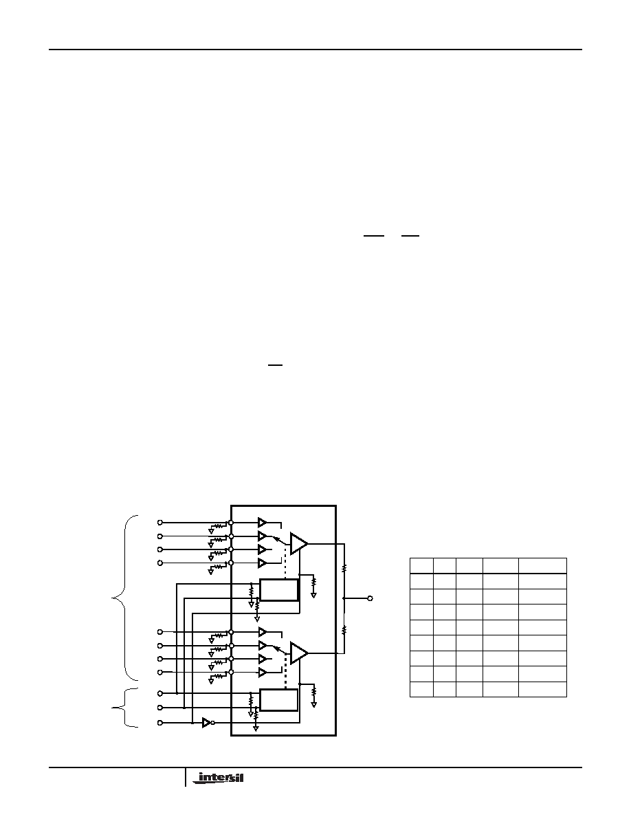
8:1 RGB Dual Gain Video MUX
The triple input RGB 8:1 MUX (Figure 44) connects the RGB
amplifier output of MUX 1 to the parallel-connected RGB
amplifier output of MUX 2 to produce a single RGB video
output. Input channels CH0 to CH3 are assigned to MUX 1
and have a throughput gain of 1. Channels CH4 through
CH7 are assigned to MUX 2 and have a throughput gain of
2. Channels CH0 through CH3 are selected by setting S2
low, which forces HIZ1 low and HIZ2 high (enables MUX 1
and three-states MUX 2). Setting S2 high reverses the logic
inputs of HIZ1, HIZ2 and switches from MUX 1 to MUX 2,
enabling the selection of channels CH4 through CH7. The
channel select inputs are parallel connected (S0-1 to S0-2)
and S1-1 to S1-2) to form two logic controls, S0 and S1. The
logic control truth table is shown in Figure 44.
FIGURE 44. APPLICATION CIRCUIT FOR A DUAL GAIN 8:1 RGB VIDEO MUX
S2
S1
S0
GAIN
OUTA, B, C
0
1
CH0A, B, C
0
1
CH1A, B, C
0
1
0
1
CH2A, B, C
0
1
CH3A, B, C
1
0
2
CH4A, B, C
1
0
1
2
CH5A, B ,C
1
0
2
CH6A, B, C
1
2
CH7A, B, C
+2
+1
ISL59483
1/3 MUX-AMP1
1/3 MUX-AMP2
OUTA
OUTA1
IN0A1
OUTA2
IN1A2
IN1A1
IN2A1
IN3A1
IN0A2
IN2A2
IN3A2
S0-1
S1-1
HIZ1
S0-2
S1-2
HIZ2
CH0
CH1
CH2
CH3
CH4
CH5
CH6
CH7
S0
S1
S2
CH0A - CH7A
CHANNEL SELECT
CHANNELS B & C
NOT SHOWN
LOGIC INPUTS
CHANNEL SELECT TRUTH TABLE
8:1 VIDEO MUX
CONTROL
LOGIC
* ROUTA1
* ROUTA2
* OPTIONAL - DEPENDING ON PARASITIC CAPACITANCE
CONTROL
LOGIC
ISL59483
相关PDF资料 |
PDF描述 |
|---|---|
| ISL59605IRZ-T7A | IC VIDEO EQUALIZER 20-QFN |
| ISL59830AIAZ-T7 | IC VIDEO DRIVER TRUE SGL 16-QSOP |
| ISL59830IA | IC DRIVER VIDEO SGL 3.3V 16-QSOP |
| ISL59832IRZ | IC VIDEO FILTER CHRG PUMP 16TQFN |
| ISL59833IAZ-T7 | IC VIDEO DRIVER TRUE SGL 16-QSOP |
相关代理商/技术参数 |
参数描述 |
|---|---|
| ISL59483IRZ-T13 | 功能描述:IC MUX AMP DUAL 500MHZ 48-QFN RoHS:是 类别:集成电路 (IC) >> 线性 - 放大器 - 视频放大器和频缓冲器 系列:- 标准包装:1,000 系列:- 应用:驱动器 输出类型:差分 电路数:3 -3db带宽:350MHz 转换速率:1000 V/µs 电流 - 电源:14.5mA 电流 - 输出 / 通道:60mA 电压 - 电源,单路/双路(±):5 V ~ 12 V,±2.5 V ~ 6 V 安装类型:表面贴装 封装/外壳:20-VFQFN 裸露焊盘 供应商设备封装:20-QFN 裸露焊盘(4x4) 包装:带卷 (TR) |
| ISL59530 | 制造商:INTERSIL 制造商全称:Intersil Corporation 功能描述:16x16 Video Crosspoint |
| ISL59530_07 | 制造商:INTERSIL 制造商全称:Intersil Corporation 功能描述:16x16 Video Crosspoint |
| ISL59530_0708 | 制造商:INTERSIL 制造商全称:Intersil Corporation 功能描述:16x16 Video Crosspoint |
| ISL59530_11 | 制造商:INTERSIL 制造商全称:Intersil Corporation 功能描述:16x16 Video Crosspoint |
发布紧急采购,3分钟左右您将得到回复。