- 您现在的位置:买卖IC网 > PDF目录19710 > ISL6142IB (Intersil)IC CTRLR HOT PLUG NEG 14-SOIC PDF资料下载
参数资料
| 型号: | ISL6142IB |
| 厂商: | Intersil |
| 文件页数: | 17/23页 |
| 文件大小: | 0K |
| 描述: | IC CTRLR HOT PLUG NEG 14-SOIC |
| 标准包装: | 50 |
| 类型: | 热交换控制器 |
| 应用: | 通用型 VoIP |
| 内部开关: | 无 |
| 电源电压: | 36 V ~ 72 V |
| 工作温度: | -40°C ~ 85°C |
| 安装类型: | 表面贴装 |
| 封装/外壳: | 14-SOIC(0.154",3.90mm 宽) |
| 供应商设备封装: | 14-SOICN |
| 包装: | 管件 |
�� �
�
�ISL6142,� ISL6152�
�Inrush� Current� Control�
�The� primary� function� of� the� ISL6142/52� hot� plug� controller� is�
�to� control� the� inrush� current.� When� a� board� is� plugged� into� a�
�live� backplane,� the� input� capacitors� of� the� board’s� power�
�supply� circuit� can� produce� large� current� transients� as� they�
�charge� up.� This� can� cause� glitches� on� the� system� power�
�supply� (which� can� affect� other� boards!),� as� well� as� possibly�
�cause� some� permanent� damage� to� the� power� supply.�
�The� key� to� allowing� boards� to� be� inserted� into� a� live� backplane�
�is� to� turn� on� the� power� to� the� board� in� a� controlled� manner,�
�usually� by� limiting� the� current� allowed� to� flow� through� a� FET�
�switch,� until� the� input� capacitors� are� fully� charged.� At� that�
�point,� the� FET� is� fully� on,� for� the� smallest� voltage� drop� across�
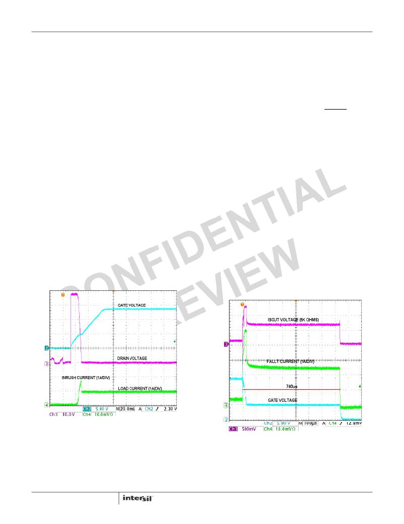
�it.� Figure� 31� illustrates� the� typical� inrush� current� response� for� a�
�hot� insertion� under� the� following� conditions:�
�V� IN� =� -48V,� Rsense� =� 0.02W�
�Current� limit� =� 50mV/0.02� ?� =� 2.5A�
�C1� =� 150nF,� C2� =� 3.3nF,� R3� =� 18k� ?�
�CL� =� 100μF,� RL� =� 50� ?� ,� I� LOAD� =� 48V/50� ?� ~1.0A�
�I� inrush� =� 50μA� (100μF/3.3nF)� =� 1.5A�
�After� the� contact� bounce� subsides� the� UVLO� and� UV� criteria�
�are� quickly� met� and� the� GATE� begins� to� ramp� up.� As� the�
�GATE� reaches� approximately� 4V� with� respect� to� the� source,�
�the� FET� begins� to� turn� on� allowing� current� to� charge� the�
�100μF� load� capacitor.� As� the� drain� to� source� voltage� begins� to�
�drop,� the� feedback� network� of� C2� and� R3� hold� the� GATE�
�constant,� in� this� case� limiting� the� current� to� approximately�
�1.5A.� When� the� DRAIN� voltage� completes� its� ramp� down,� the�
�load� current� remains� constant� at� approximately� 1.0A� as� the�
�GATE� voltage� increases� to� its� final� value.�
�circuit� breaker� is� capable� of� detecting� both� hard� faults,� and�
�less� severe� Over-Current� conditions.�
�The� Over-Current� trip� point� is� determined� by� R1� Equation� 3)�
�also� referred� to� as� Rsense.� When� the� voltage� across� this�
�resistor� exceeds� 50mV,� the� current� limit� regulator� will� turn� on,�
�and� the� GATE� will� be� pulled� lower� (to� ~4V)� to� regulate� current�
�through� the� FET� at� 50mV/Rsense.� If� the� fault� persists� and�
�current� limiting� exceeds� the� programmed� time-out� period,� the�
�FET� will� be� turned� off� by� discharging� the� GATE� pin� to� V� EE� .�
�This� will� set� the� Over-Current� latch� and� the� PWRGD/PWRGD�
�output� will� transition� to� the� inactive� state,� indicating� power� is�
�no� longer� good.� To� clear� the� latch� and� initiate� a� normal� start-�
�up� sequence,� the� user� must� either� power� down� the� system�
�(below� the� UVLO� voltage),� toggle� the� UV� pin� below� and� above�
�its� threshold� (usually� with� an� external� transistor),� or� toggle� the�
�DIS� pin� high� to� low.� Figure� 32� shows� the� Over-Current� shut�
�down� and� current� limiting� response� for� a� 10� ?� short� to� ground�
�on� the� output.� Prior� to� the� short� circuit� the� output� load� is� 110� ?�
�producing� an� operating� current� of� about� 0.44A� (48V/110� ?� ).� A�
�10� ?� short� is� then� applied� to� the� output� causing� an� initial� fault�
�current� of� 4.8A.� This� produces� a� voltage� drop� across� the�
�0.02� ?� sense� resistor� of� approximately� 95mV,� roughly� two�
�times� the� Over-Current� threshold� of� 50mV.� The� GATE� is�
�quickly� pulled� low� to� limit� the� current� to� 2.5A� (50mV/Rsense)�
�and� the� timer� is� enabled.� The� fault� condition� persists� for� the�
�duration� of� the� programmed� time-out� period� (C3� =� 1500pF)�
�and� the� GATE� is� latched� off� in� about� 740μs.� There� is� a� short�
�filter� (3μs� nominal)� on� the� comparator,� so� current� transients�
�shorter� than� this� will� be� ignored.� Longer� transients� will� initiate�
�the� GATE� pull� down,� current� limiting,� and� the� timer.� If� the� fault�
�current� goes� away� before� the� time-out� period� expires� the�
�device� will� exit� the� current� limiting� mode� and� resume� normal�
�operation.�
�FIGURE� 31.� HOT� INSERTION� INRUSH� CURRENT� LIMITING,�
�DISABLE� PIN� TIED� TO� V� EE�
�Electronic� Circuit� Breaker/Current� Limit�
�The� ISL6142/52� allows� the� user� to� program� both� the� current�
�limit� and� the� time-out� period� to� protect� the� system� against�
�excessive� supply� or� fault� currents.� The� IntelliTrip?� electronic�
�FIGURE� 32.� CURRENT� LIMITING� AND� TIME-OUT�
�In� addition� to� current� limiting� and� programmable� time-out,�
�there� is� a� hard� fault� comparator� to� respond� to� short� circuits�
�with� an� immediate� GATE� shutdown� (typically� 10� μ� s)� and� a�
�single� retry.� The� trip� point� of� this� comparator� is� set� ~4� times�
�(210mV)� higher� than� the� Over-Current� threshold� of� 50mV.� If�
�17�
�相关PDF资料 |
PDF描述 |
|---|---|
| MIC3975-5.0BMM | IC REG LDO 5V .75A 8-MSOP |
| ISL6141IB-T | IC CTRLR HOT PLUG NEG VOLT 8SOIC |
| AMM15DTAN | CONN EDGECARD 30POS R/A .156 SLD |
| LC5512MV-45F484C | IC XPLD 512MC 4.5NS 484FPBGA |
| 180-015-202L011 | CONN DB15 FEMALE HD SLD CUP TIN |
相关代理商/技术参数 |
参数描述 |
|---|---|
| ISL6142IB-T | 功能描述:IC CTRLR HOT PLUG NEG 14-SOIC RoHS:否 类别:集成电路 (IC) >> PMIC - 热交换 系列:- 产品培训模块:Obsolescence Mitigation Program 标准包装:100 系列:- 类型:热插拔开关 应用:通用 内部开关:是 电流限制:可调 电源电压:9 V ~ 13.2 V 工作温度:-40°C ~ 150°C 安装类型:表面贴装 封装/外壳:10-WFDFN 裸露焊盘 供应商设备封装:10-TDFN-EP(3x3) 包装:管件 |
| ISL6142IBZA | 功能描述:IC CTRLR HOT PLUG NEG 14-SOIC RoHS:是 类别:集成电路 (IC) >> PMIC - 热交换 系列:- 产品培训模块:Obsolescence Mitigation Program 标准包装:100 系列:- 类型:热插拔开关 应用:通用 内部开关:是 电流限制:可调 电源电压:9 V ~ 13.2 V 工作温度:-40°C ~ 150°C 安装类型:表面贴装 封装/外壳:10-WFDFN 裸露焊盘 供应商设备封装:10-TDFN-EP(3x3) 包装:管件 |
| ISL6142IBZA-T | 功能描述:IC CTRLR HOT PLUG NEG 14-SOIC RoHS:是 类别:集成电路 (IC) >> PMIC - 热交换 系列:- 产品培训模块:Obsolescence Mitigation Program 标准包装:100 系列:- 类型:热插拔开关 应用:通用 内部开关:是 电流限制:可调 电源电压:9 V ~ 13.2 V 工作温度:-40°C ~ 150°C 安装类型:表面贴装 封装/外壳:10-WFDFN 裸露焊盘 供应商设备封装:10-TDFN-EP(3x3) 包装:管件 |
| ISL6144 | 制造商:INTERSIL 制造商全称:Intersil Corporation 功能描述:High Voltage ORing MOSFET Controller |
| ISL6144_07 | 制造商:INTERSIL 制造商全称:Intersil Corporation 功能描述:High Voltage ORing MOSFET Controller |
发布紧急采购,3分钟左右您将得到回复。