- 您现在的位置:买卖IC网 > PDF目录19800 > ISL6174IRZ-T (Intersil)IC CIRC BREAKER DUAL LV 28-QFN PDF资料下载
参数资料
| 型号: | ISL6174IRZ-T |
| 厂商: | Intersil |
| 文件页数: | 11/16页 |
| 文件大小: | 346K |
| 描述: | IC CIRC BREAKER DUAL LV 28-QFN |
| 标准包装: | 6,000 |
| 类型: | 热交换控制器 |
| 应用: | 通用 |
| 内部开关: | 无 |
| 电源电压: | 2.25 V ~ 3.63 V |
| 工作温度: | -40°C ~ 85°C |
| 安装类型: | 表面贴装 |
| 封装/外壳: | 28-VFQFN 裸露焊盘 |
| 供应商设备封装: | 28-QFN 裸露焊盘(5x5) |
| 包装: | 带卷 (TR) |
11
FN6830.0
December 19, 2008
Current Set Resistor (R
SET
)
This resistor sets the threshold for the Circuit Breaker
comparator in conjunction with R
SNS
. Once R
SNS
has been
selected, use Equation 1 to calculate R
SET
. Use 20礎 for
I
SET
in a typical application.
Reference Current Set Resistor (R
REF
)
This resistor sets up the current in the internal current
source, I
REF
/4, shown in Figure 2 for the comparators. The
voltage at the OCREF pin is the same as the internal
bandgap reference. The current (I
REF
) flowing through this
resistor is simply:
I
REF
= 1.178/R
REF
This current, I
REF
, should be set at 80礎 to force 20礎 in the
internal current source as shown in Figure 2, because of the
4:1 current mirror. This equates to the resistor value of
14.7k.
Selection of Rs1 and Rs2
These resistors set the UV detect point. The UV comparator
detects the undervoltage condition when it sees the voltage
at UV pin drop below 0.633V. The resistor divider values
should be selected accordingly.
Charge Pump Capacitor Selection (C
P
and C
V
)
C
P
is the
flying cap
and C
V
is the smoothing cap of the
charge pump, which operates at 450kHz set internally. The
output resistance of the charge pump, which affects the
regulation, is dependent on the C
P
value and its ESR,
charge-pump switch resistance, and the frequency and ESR
of the smoothing cap, C
V
.
It is recommended that C
P
be kept within 0.022礔
(minimum) to 0.1礔 (maximum) range. Only ceramic
capacitors are recommended. Use 0.1礔 cap if CPVDD
output is expected to power an external circuit, in which case
the current draw from CPVDD must be kept below 10mA.
C
V
should at least be 0.47礔 (ceramic only). Higher values
may be used if low ripple performance is desired.
Time-out Capacitor Selection (C
T
)
This capacitor determines the current regulation delay
period. As shown in Figure 2, when the voltage across this
capacitor exceeds 1.178V, the time-out comparator detects it
and the gate voltage is pulled to 0V thus shutting down the
channel. An internal 10礎 current source charges this
capacitor. Hence, the value of this capacitor is determined by
Equation 2.
Where,
T
OUT
= Desired time-out period.
Soft-Start Capacitor Selection (C
SS
)
The rate of change of voltage (dv/dt) on this capacitor, which
is determined by the internal 10礎 current source, is the
same as that on the output load capacitance. Hence, the
value of this capacitor directly controls the inrush current
amplitude during hot swap operation.
Where,
C
O
= Load Capacitance
I
INRUSH
= Desired Inrush Current
I
INRUSH
is the sum of the DC steady-state load current and
the load capacitance charging current. If the DC steady-state
load remains disabled until after the soft-start period expires
(PGx
could be used as a load enable signal, for example),
then only the capacitor charging current should be used as
I
INRUSH
. The Css value should always be more than (1/2.4)
of that of Ciss of the MOSFET to ensure proper soft-start
operation. This is because the Ciss is charged from 24礎
current source, whereas the Css gets charged from a 10礎
current source (Figure 15). In order to make sure both V
SS
and V
O
track during the soft-start, this condition is
necessary.
ISL6174 Evaluation Platform
The ISL617XEVAL1Z is the primary evaluation board for this
IC. For the BOM, schematic and photograph, see the
BOM
for ISL617XEVAL1Z Board and Schematic
on page 15.
The evaluation board has been designed with a typical
application in mind and with accessibility to all the featured
pins to enable a user to understand and verify these features
of the IC. The two circuit breaker levels are programmed to
2.2A for each input rail but they can easily be scaled up or
down by adjusting some component values.
There are two input voltages, one for each channel that are
switched by a dual N-Channel MOSFET (Q1) to the output
connectors.
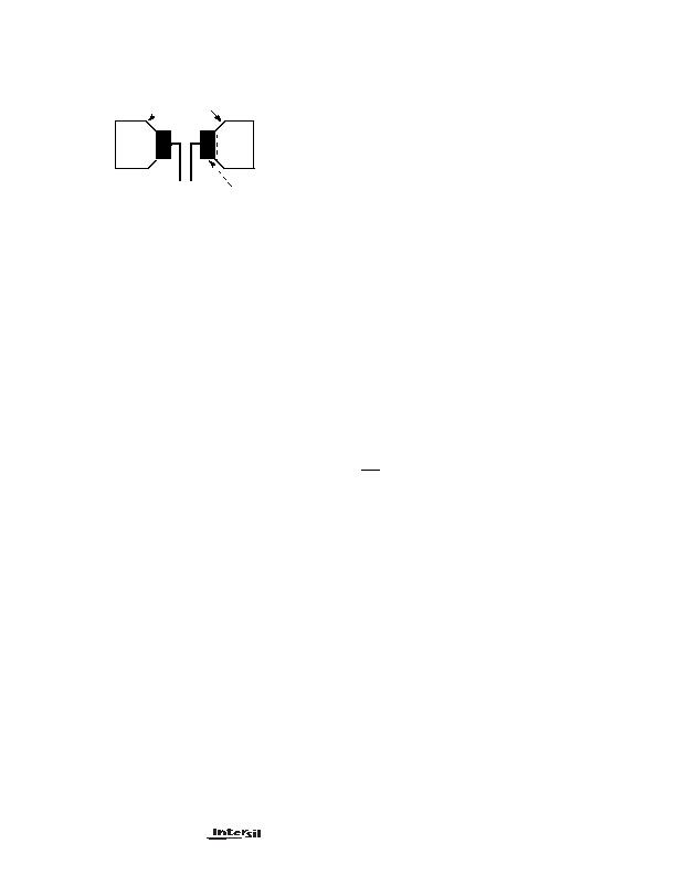
LOAD CURRENT CARRYING
TRACES
R
SNS
CURRENT
SENSE
TRACES
FIGURE 17. RECOMMENDED CURRENT SENSE RESISTOR
PCB LAYOUT
C
T
10糀 T
OUT
"
(
) 1.178
D
=
(EQ. 2)
C
SS
C
O
10糀 I
INRUSH
D
(
)
"
=
(EQ. 3)
ISL6174
相关PDF资料 |
PDF描述 |
|---|---|
| MIC2086-LBQS TR | IC CTRLR HOW SWAP SGL 20-QSOP |
| VI-J50-CW-B1 | CONVERTER MOD DC/DC 5V 100W |
| TAJA335M016RNJ | CAP TANT 3.3UF 16V 20% 1206 |
| MIC39301-1.8BU | IC REG LDO 1.8V 3A TO263-5 |
| TEA1530AP/N2,112 | IC CTRLR SMPS GREEN OVP OTP 8DIP |
相关代理商/技术参数 |
参数描述 |
|---|---|
| ISL617XEVAL1Z | 制造商:INTERSIL 制造商全称:Intersil Corporation 功能描述:Dual Low Voltage Circuit Breaker |
| ISL6185 | 制造商:INTERSIL 制造商全称:Intersil Corporation 功能描述:Dual USB Port Power Supply Controller |
| ISL6185_11 | 制造商:INTERSIL 制造商全称:Intersil Corporation 功能描述:Dual USB Port Power Supply Controller 2.5V to 5V Operating Range |
| ISL61851ACBZ | 功能描述:热插拔功率分布 DL USB HOTSWAP W/INT FET-EN HI 8LD RoHS:否 制造商:Texas Instruments 产品:Controllers & Switches 电流限制: 电源电压-最大:7 V 电源电压-最小:- 0.3 V 工作温度范围: 功率耗散: 安装风格:SMD/SMT 封装 / 箱体:MSOP-8 封装:Tube |
| ISL61851ACBZ-T | 功能描述:热插拔功率分布 DL USB HOTSWAP W/INT FET-EN HI 8LD RoHS:否 制造商:Texas Instruments 产品:Controllers & Switches 电流限制: 电源电压-最大:7 V 电源电压-最小:- 0.3 V 工作温度范围: 功率耗散: 安装风格:SMD/SMT 封装 / 箱体:MSOP-8 封装:Tube |
发布紧急采购,3分钟左右您将得到回复。