- 您现在的位置:买卖IC网 > PDF目录15495 > ISL6224CAZ (Intersil)IC REG CTRLR BUCK PWM CM 16-SSOP PDF资料下载
参数资料
| 型号: | ISL6224CAZ |
| 厂商: | Intersil |
| 文件页数: | 7/13页 |
| 文件大小: | 0K |
| 描述: | IC REG CTRLR BUCK PWM CM 16-SSOP |
| 标准包装: | 98 |
| PWM 型: | 电流模式 |
| 输出数: | 1 |
| 频率 - 最大: | 690kHz |
| 占空比: | 94% |
| 电源电压: | 4.75 V ~ 5.25 V |
| 降压: | 是 |
| 升压: | 无 |
| 回扫: | 无 |
| 反相: | 无 |
| 倍增器: | 无 |
| 除法器: | 无 |
| Cuk: | 无 |
| 隔离: | 无 |
| 工作温度: | -10°C ~ 85°C |
| 封装/外壳: | 16-SSOP(0.154",3.90mm 宽) |
| 包装: | 管件 |
| 产品目录页面: | 1243 (CN2011-ZH PDF) |
�� �
�
�ISL6224�
�due� to� the� voltage� drop� on� the� output� capacitor� ESR.� If� the�
�VOUT�
�I� L�
�t�
�t�
�decrease� causes� the� output� voltage� to� drop� below� the�
�hysteretic� regulation� level,� the� mode� is� changed� to� PWM� on�
�the� next� clock� cycle.� This� insures� the� full� power� required� by�
�the� increase� in� output� current.�
�PHASE�
�COMP�
�MODE�
�OF�
�OPERATION�
�1� 2� 3� 4� 5� 6� 7� 8�
�PWM�
�HYSTERETIC�
�t�
�t�
�I� L�
�t�
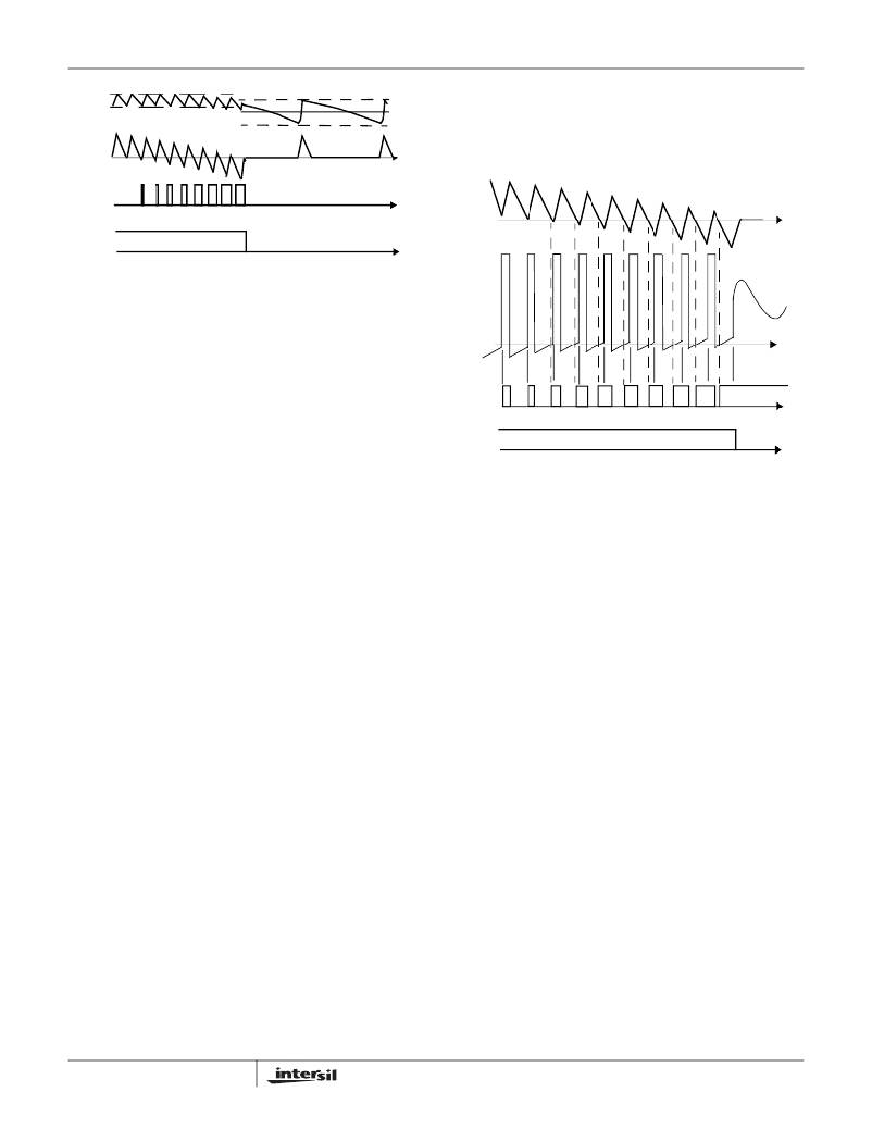
�FIGURE� 2.� HYSTERETIC� OPERATION� MODE�
�Operation-Mode� Control�
�The� mode-control� circuit� changes� the� converter� ’s� mode� of�
�operation� based� on� the� voltage� polarity� of� the� phase� node�
�PHASE�
�NODE�
�t�
�when� the� lower� MOSFET� is� conducting� and� just� before� the�
�upper� MOSFET� turns� on.� For� continuous� inductor� current,�
�the� phase� node� is� negative� when� the� lower� MOSFET� is�
�conducting� and� the� converters� operate� in� fixed-frequency�
�PHASE�
�COMP�
�1�
�2�
�3�
�4�
�5�
�6�
�7�
�8�
�t�
�PWM� mode� as� shown� in� Figure� 3.� When� the� load� current�
�decreases� to� the� point� where� the� inductor� current� flows�
�MODE�
�OF�
�OPERATION�
�PWM�
�HYSTERETIC�
�t�
�through� the� lower� MOSFET� in� the� ‘reverse’� direction,� the�
�phase� node� becomes� positive,� and� the� mode� is� changed� to�
�hysteretic.�
�A� phase� comparator� handles� the� timing� of� the� phase� node�
�voltage� sensing.� A� low� level� on� the� phase� comparator� output�
�indicates� a� negative� phase� voltage� during� the� conduction�
�time� of� the� lower� MOSFET.� A� high� level� on� the� phase�
�comparator� output� indicates� a� positive� phase� voltage.�
�When� the� phase� node� is� positive� (phase� comparator� high),�
�at� the� end� of� the� lower� MOSFET� conduction� time,� for� eight�
�consecutive� clock� cycles,� the� mode� is� changed� to� hysteretic�
�as� shown� in� Figure� 3.� The� dashed� lines� indicate� when� the�
�phase� node� goes� positive� and� the� phase� comparator� output�
�goes� high.� The� solid� vertical� lines� at� 1,2,...8� indicate� the�
�sampling� time,� of� the� phase� comparator,� to� determine� the�
�polarity� (sign)� of� the� phase� node.� At� the� transition� between�
�PWM� and� hysteretic� mode� both� the� upper� and� lower�
�MOSFETs� are� turned� off.� The� phase� node� will� ‘ring’� based�
�on� the� output� inductor� and� the� parasitic� capacitance� on� the�
�phase� node� and� settle� out� at� the� value� of� the� output� voltage.�
�The� mode� change� from� hysteretic� to� PWM� can� be� caused� by�
�one� of� two� events.� One� event� is� the� same� mechanism� that�
�causes� a� PWM� to� hysteretic� transition.� But� instead� of� looking�
�for� eight� consecutive� positive� occurrences� on� the� phase�
�node,� it� is� looking� for� eight� consecutive� negative�
�occurrences� on� the� phase� node.� The� operation� mode� will� be�
�changed� from� hysteretic� to� PWM� when� these� eight�
�consecutive� pulses� occur.� This� transition� technique� prevents�
�jitter� of� the� operation� mode� at� load� levels� close� to� boundary.�
�The� other� mechanism� for� changing� from� hysteretic� to� PWM�
�is� due� to� a� sudden� increase� in� the� output� current.� This� step�
�load� causes� an� instantaneous� decrease� in� the� output� voltage�
�7�
�FIGURE� 3.� MODE� CONTROL� WAVEFORMS�
�Gate� Control� Logic�
�The� gate� control� logic� translates� generated� PWM� control�
�signals� into� the� MOSFET� gate� drive� signals� providing�
�necessary� amplification,� level� shifting� and� shoot-through�
�protection.� Also,� it� has� functions� that� help� optimize� the� IC�
�performance� over� a� wide� range� of� operational� conditions.�
�Since� MOSFET� switching� time� can� vary� dramatically� from�
�type� to� type� and� with� the� input� voltage,� the� gate� control� logic�
�provides� adaptive� dead� time� by� monitoring� the� gate-to-�
�source� voltages� of� both� upper� and� lower� MOSFETs.� The�
�lower� MOSFET� is� not� turned� on� until� the� gate-to-source�
�voltage� of� the� upper� MOSFET� has� decreased� to� less� than�
�approximately� 1V.� Similarly,� the� upper� MOSFET� is� not� turned�
�on� until� the� gate-to-source� voltage� of� the� lower� MOSFET� has�
�decreased� to� less� than� approximately� 1V.� This� allows� a� wide�
�variety� of� upper� and� lower� MOSFETs� to� be� used� without� a�
�concern� for� simultaneous� conduction,� or� shoot-through.�
�FN9042.8�
�June� 8,� 2006�
�相关PDF资料 |
PDF描述 |
|---|---|
| ISL8118CRZ | IC REG CTRLR BUCK PWM VM 28-QFN |
| EMC13DRYI | CONN EDGECARD 26POS .100 EXTEND |
| ESC19DRTN | CONN EDGECARD 38POS DIP .100 SLD |
| EMC15DRTN | CONN EDGECARD 30POS .100 EXTEND |
| ISL6843IUZ | IC REG CTRLR BST FLYBK ISO 8MSOP |
相关代理商/技术参数 |
参数描述 |
|---|---|
| ISL6224CAZA | 制造商:INTERSIL 制造商全称:Intersil Corporation 功能描述:Single Output Mobile-Friendly PWM Controller |
| ISL6224CAZA-T | 制造商:INTERSIL 制造商全称:Intersil Corporation 功能描述:Single Output Mobile-Friendly PWM Controller |
| ISL6224CAZ-T | 功能描述:电流型 PWM 控制器 MOBILE PWM CNTRLR 16-PIN SSOP RoHS:否 制造商:Texas Instruments 开关频率:27 KHz 上升时间: 下降时间: 工作电源电压:6 V to 15 V 工作电源电流:1.5 mA 输出端数量:1 最大工作温度:+ 105 C 安装风格:SMD/SMT 封装 / 箱体:TSSOP-14 |
| ISL6224EVAL1 | 制造商:Intersil Corporation 功能描述:DEV TOOLS, EVAL BD FOR SGL OUTPUT MOBILE-FRIENDLY PWM CNTRLR - Bulk |
| ISL6225 | 制造商:INTERSIL 制造商全称:Intersil Corporation 功能描述:Dual Mobile-Friendly PWM Controller with DDR Memory Option |
发布紧急采购,3分钟左右您将得到回复。