- 您现在的位置:买卖IC网 > PDF目录15495 > ISL6224CAZ (Intersil)IC REG CTRLR BUCK PWM CM 16-SSOP PDF资料下载
参数资料
| 型号: | ISL6224CAZ |
| 厂商: | Intersil |
| 文件页数: | 8/13页 |
| 文件大小: | 0K |
| 描述: | IC REG CTRLR BUCK PWM CM 16-SSOP |
| 标准包装: | 98 |
| PWM 型: | 电流模式 |
| 输出数: | 1 |
| 频率 - 最大: | 690kHz |
| 占空比: | 94% |
| 电源电压: | 4.75 V ~ 5.25 V |
| 降压: | 是 |
| 升压: | 无 |
| 回扫: | 无 |
| 反相: | 无 |
| 倍增器: | 无 |
| 除法器: | 无 |
| Cuk: | 无 |
| 隔离: | 无 |
| 工作温度: | -10°C ~ 85°C |
| 封装/外壳: | 16-SSOP(0.154",3.90mm 宽) |
| 包装: | 管件 |
| 产品目录页面: | 1243 (CN2011-ZH PDF) |
�� �
�
�ISL6224�
�1.5V� � Css�
�5.0� μ� A�
�L� O� � I� TRAN� I� TRAN�
�(� V� IN� –� V� OUT� )� ×� 2�
�C� OUT� =� ----------------------------------------------� � --------------------�
�Soft-Start� Operation�
�Soft-start� of� the� Synchronous� Buck� Converter� is�
�accomplished� by� means� of� a� capacitor� connected� from� pin� 7,�
�SOFT� to� ground.� The� soft-start� time� can� be� obtained� from�
�the� following� equation:�
�Tss� =� ------------------------------�
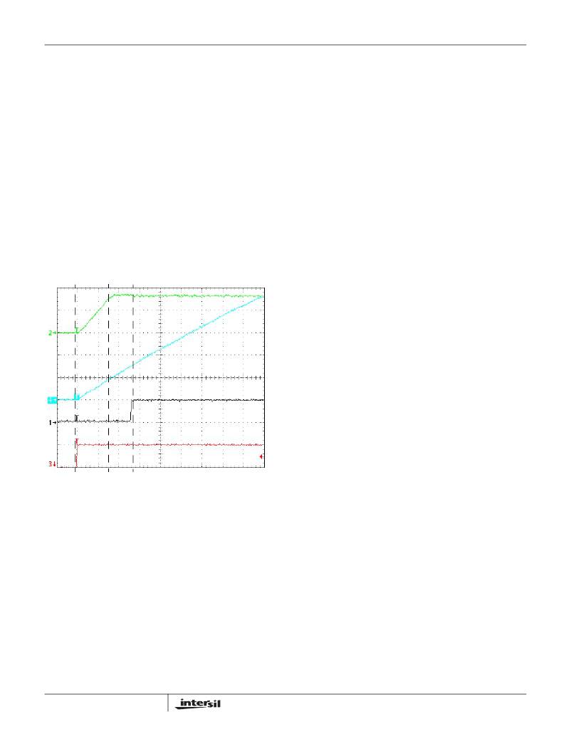
�Figure� 4� shows� the� soft-start� initiated� by� the� ENABLE� pin�
�being� pulled� high� with� the� VIN� input� at� 5.6V� and� the� resulting�
�3.3V� output� and� PGOOD� signal.� While� the� ENABLE� pin� is�
�held� low,� prior� to� t0,� the� output� is� off.� When� the� EN� pin� is�
�pulled� high,� at� t0,� the� voltage� on� the� capacitor� connected� to�
�the� soft-start� pin� rises� linearly� due� to� the� internal� 5� μ� A� current�
�source� starts� charging� the� capacitor.� The� output� voltage�
�follows� the� voltage� on� the� capacitor� till� it� reaches� the� value� of�
�0.9V� at� t1.� At� this� moment,� t1,� the� output� voltage� started�
�regulation.� The� soft-start� is� complete� when� PGOOD� pin� is�
�high� at� t2� and� further� rise� of� the� voltage� on� the� soft-start�
�capacitor� does� not� affect� the� output� voltage.�
�This� ‘soft-crowbar� ’� and� monitoring� of� the� output,� prevents� the�
�output� voltage� from� ringing� negative� as� the� inductor� current�
�flows� in� the� ‘reverse’� direction� through� the� lower� MOSFET�
�and� output� capacitors.�
�Component� Selection� Guidelines�
�Output� Capacitor� Selection�
�The� output� capacitors� have� unique� requirements.� In� general,�
�the� output� capacitors� should� be� selected� to� meet� the�
�dynamic� regulation� requirements� including� ripple� voltage�
�and� load� transients.�
�Selection� of� the� output� capacitors� is� also� dependent� on� the�
�output� inductor� so� some� inductor� analysis� is� required� to�
�select� the� output� capacitors.�
�One� of� the� parameters� limiting� the� converter� ’s� response� to� a�
�load� transient� is� the� time� required� for� the� inductor� current� to�
�slew� to� its� new� level.� Given� a� sufficiently� fast� control� loop�
�design,� the� ISL6224� will� provide� either� 0%� or� 94%� duty� cycle�
�in� response� to� a� load� transient.� The� response� time� is� the�
�time� interval� required� to� slew� the� inductor� current� from� an�
�initial� current� value� to� the� load� current� level.� During� this�
�interval� the� difference� between� the� inductor� current� and� the�
�transient� current� level� must� be� supplied� by� the� output�
�capacitor(s).� Minimizing� the� response� time� can� minimize� the�
�output� capacitance� required.� If� the� load� transient� rise� time� is�
�slower� than� the� inductor� response� time,� as� in� a� hard� drive� or�
�CD� drive,� this� reduces� the� requirement� on� the� output�
�capacitor.�
�The� maximum� capacitor� value� required� to� provide� the� full,�
�rising� step,� transient� load� current� during� the� response� time� of�
�the� inductor� is:�
�DV� OUT�
�Where:� C� OUT� is� the� output� capacitor(s)� required,� L� O� is� the�
�t0�
�t1�
�t2�
�output� inductor,� I� TRAN� is� the� transient� load� current� step,� V� IN�
�FIGURE� 4.� MODE� CONTROL� WAVEFORMS�
�Power� Good� Status�
�The� ISL6224� monitors� the� output� voltage.� A� single� power-�
�good� signal,� PGOOD,� is� issued� when� soft-start� is� completed�
�and� the� output� is� within� 10%� of� it’s� set� point.� After� the� soft-�
�start� sequence� is� completed,� undervoltage� protection�
�latches� the� chip� off� when� any� of� the� monitored� outputs� drop�
�below� 70%� of� its� set� point.�
�A� ‘soft-crowbar� ’� function� is� implemented� for� an� overvoltage�
�on� the� output.� If� the� output� voltage� goes� above� 120%� of� its�
�nominal� output� level,� the� upper� MOSFET� is� turned� off� and�
�the� lower� MOSFET� is� turned� on.� This� ‘soft-crowbar� ’�
�condition� will� be� maintained� until� the� output� voltage� returns�
�to� the� regulation� window� and� then� normal� operation� will�
�continue.�
�8�
�is� the� input� voltage,� V� OUT� is� output� voltage,� and� DV� OUT� is�
�the� drop� in� output� voltage� allowed� during� the� load� transient.�
�High� frequency� capacitors� initially� supply� the� transient�
�current� and� slow� the� load� rate-of-change� seen� by� the� bulk�
�capacitors.� The� bulk� filter� capacitor� values� are� generally�
�determined� by� the� ESR� (equivalent� series� resistance)� and�
�voltage� rating� requirements� as� well� as� actual� capacitance�
�requirements.� The� output� voltage� ripple� is� due� to� the� inductor�
�ripple� current� and� the� ESR� of� the� output� capacitors� as�
�defined� by:�
�V� RIPPLE� =� ?� I� L� � ESR�
�where,� ?� I� L� is� calculated� in� the� Inductor� Selection� section.�
�High� frequency� decoupling� capacitors� should� be� placed� as�
�close� to� the� power� pins� of� the� load� as� physically� possible.� Be�
�careful� not� to� add� inductance� in� the� circuit� board� wiring� that�
�FN9042.8�
�June� 8,� 2006�
�相关PDF资料 |
PDF描述 |
|---|---|
| ISL8118CRZ | IC REG CTRLR BUCK PWM VM 28-QFN |
| EMC13DRYI | CONN EDGECARD 26POS .100 EXTEND |
| ESC19DRTN | CONN EDGECARD 38POS DIP .100 SLD |
| EMC15DRTN | CONN EDGECARD 30POS .100 EXTEND |
| ISL6843IUZ | IC REG CTRLR BST FLYBK ISO 8MSOP |
相关代理商/技术参数 |
参数描述 |
|---|---|
| ISL6224CAZA | 制造商:INTERSIL 制造商全称:Intersil Corporation 功能描述:Single Output Mobile-Friendly PWM Controller |
| ISL6224CAZA-T | 制造商:INTERSIL 制造商全称:Intersil Corporation 功能描述:Single Output Mobile-Friendly PWM Controller |
| ISL6224CAZ-T | 功能描述:电流型 PWM 控制器 MOBILE PWM CNTRLR 16-PIN SSOP RoHS:否 制造商:Texas Instruments 开关频率:27 KHz 上升时间: 下降时间: 工作电源电压:6 V to 15 V 工作电源电流:1.5 mA 输出端数量:1 最大工作温度:+ 105 C 安装风格:SMD/SMT 封装 / 箱体:TSSOP-14 |
| ISL6224EVAL1 | 制造商:Intersil Corporation 功能描述:DEV TOOLS, EVAL BD FOR SGL OUTPUT MOBILE-FRIENDLY PWM CNTRLR - Bulk |
| ISL6225 | 制造商:INTERSIL 制造商全称:Intersil Corporation 功能描述:Dual Mobile-Friendly PWM Controller with DDR Memory Option |
发布紧急采购,3分钟左右您将得到回复。