- 您现在的位置:买卖IC网 > PDF目录17237 > ISL62392LOEVAL1Z (Intersil)EVALUATION BOARD FOR ISL62392LO PDF资料下载
参数资料
| 型号: | ISL62392LOEVAL1Z |
| 厂商: | Intersil |
| 文件页数: | 14/21页 |
| 文件大小: | 0K |
| 描述: | EVALUATION BOARD FOR ISL62392LO |
| 标准包装: | 1 |
| 系列: | Robust Ripple Regulator™ (R³) |
| 主要目的: | DC/DC,LDO 步降 |
| 输出及类型: | 3,非隔离 |
| 输出电压: | 3.3V,5V,3.3V |
| 电流 - 输出: | 8A,8A,100mA |
| 输入电压: | 5.5 ~ 25 V |
| 稳压器拓扑结构: | 降压 |
| 板类型: | 完全填充 |
| 已供物品: | 板 |
| 已用 IC / 零件: | ISL62392 |
�� �
�
�ISL62391,� ISL62392,� ISL62391C,� ISL62392C�
�PVCC� is� above� the� 4.2V� VCC� POR� threshold,� VCC� will�
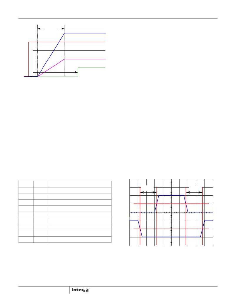
�1.5ms�
�t� SOFTSTART�
�VO�
�VCC� AND� PVCC�
�EN�
�FB�
�switchover� to� PVCC� internally.�
�After� VIN� is� applied,� the� VCC� start-up� 3.6V� voltage� can� be� used�
�as� the� logic� high� signal� of� any� of� EN1,� EN2� and� LDO3EN� to�
�enable� PVCC� if� there� is� no� other� power� supply� on� the� board.�
�MOSFET� Gate-Drive� Outputs� LGATE� and� UGATE�
�The� ISL62391,� ISL62392,� ISL62391C� and� ISL62392C� have�
�internal� gate-drivers� for� the� high-side� and� low-side� N-�
�PGOOD�
�2.75ms�
�PGOOD� DELAY�
�FIGURE� 24.� SOFT-START� SEQUENCE� FOR� ONE� SMPS�
�The� PGOOD� pin� indicates� when� the� converter� is� capable� of�
�supplying� regulated� voltage.� It� is� an� undefined� impedance� if�
�V� IN� is� not� above� the� rising� POR� threshold� or� below� the� POR�
�falling� threshold.� When� a� fault� is� detected,� the� ISL62391,�
�ISL62392,� ISL62391C� and� ISL62392C� will� turn� on� the� open-�
�drain� NMOS,� which� will� pull� PGOOD� low� with� a� nominal�
�impedance� of� 32� Ω.� This� will� flag� the� system� that� one� of� the�
�output� voltages� is� out� of� regulation.�
�Separate� enable� pins� allow� for� full� soft-start� sequencing.�
�Because� low� shutdown� quiescent� current� is� necessary� to�
�prolong� battery� life� in� notebook� applications,� the� PVCC� 5V�
�LDO� is� held� off� until� any� of� the� three� enable� signals� (EN1,�
�EN2� or� LDO3EN)� are� pulled� high.� Soft-start� of� all� outputs� will�
�only� start� until� after� PVCC� is� above� the� 4.2V� POR� threshold.�
�In� addition� to� user-programmable� sequencing,� the� ISL62391,�
�ISL62392,� ISL62391C� and� ISL62392C� include� a� pre-�
�programmed� sequential� SMPS� soft-start� feature.� Table� 1�
�shows� the� SMPS� enable� truth� table.�
�TABLE� 1.� SMPS� ENABLE� SEQUENCE� LOGIC�
�Channel� MOSFETs.� The� low-side� gate-drivers� are� optimized�
�for� low� duty-cycle� applications� where� the� low-side� MOSFET�
�conduction� losses� are� dominant,� requiring� a� low� r� DS(ON)�
�MOSFET.� The� LGATE� pull-down� resistance� is� small� in� order�
�to� clamp� the� gate� of� the� MOSFET� below� the� V� GS(th)� at� turn-�
�off.� The� current� transient� through� the� gate� at� turn-off� can� be�
�considerable� because� the� gate� charge� of� a� low� r� DS(ON)�
�MOSFET� can� be� large.� Adaptive� shoot-through� protection�
�prevents� a� gate-driver� output� from� turning� on� until� the� opposite�
�gate-driver� output� has� fallen� below� approximately� 1V.� The�
�dead-time� shown� in� Figure� 25� is� extended� by� the� additional�
�period� that� the� falling� gate� voltage� stays� above� the� 1V�
�threshold.� The� typical� dead-time� is� 21ns.� The� high-side� gate-�
�driver� output� voltage� is� measured� across� the� UGATE� and�
�PHASE� pins� while� the� low-side� gate-driver� output� voltage� is�
�measured� across� the� LGATE� and� PGND� pins.� The� power� for�
�the� LGATE� gate-driver� is� sourced� directly� from� the� PVCC� pin.�
�The� power� for� the� UGATE� gate-driver� is� sourced� from� a� “boot”�
�capacitor� connected� across� the� BOOT� and� PHASE� pins.� The�
�boot� capacitor� is� charged� from� the� 5V� PVCC� supply� through� a�
�“boot� diode”� each� time� the� low-side� MOSFET� turns� on,� pulling�
�the� PHASE� pin� low.� The� ISL62391,� ISL62392,� ISL62391C� and�
�ISL62392C� have� integrated� boot� diodes� connected� from� the�
�PVCC� pins� to� BOOT� pins.�
�EN1�
�EN2�
�START-UP� SEQUENCE�
�0�
�0�
�0�
�FLOAT�
�FLOAT�
�FLOAT�
�1�
�1�
�1�
�0�
�FLOAT�
�1�
�0�
�FLOAT�
�1�
�0�
�FLOAT�
�1�
�All� SMPS� outputs� OFF�
�All� SMPS� outputs� OFF�
�SMPS1� OFF,� SMPS2� ON�
�All� SMPS� outputs� OFF�
�All� SMPS� outputs� OFF�
�SMPS1� enables� after� SMPS2� is� in� regulation�
�SMPS1� ON,� SMPS2� OFF�
�SMPS2� enables� after� SMPS1� is� in� regulation�
�All� SMPS� outputs� ON� simultaneously�
�UGATE�
�LGATE�
�t� LGFUGR�
�50%�
�50%�
�t� UGFLGR�
�VCC�
�The� VCC� nominal� operation� voltage� is� 5V.� If� EN1,� EN2� and�
�LDO3EN� are� all� logic� low,� the� VCC� start-up� voltage� is� 3.6V�
�when� VIN� is� applied� on� ISL62391,� ISL62392,� ISL62391C�
�and� ISL62392C.� PVCC� is� held� off� until� any� of� the� three�
�enable� signals� (EN1,� EN2� or� LDO3EN)� is� pulled� high.� When�
�14�
�FIGURE� 25.� LGATE� AND� UGATE� DEAD-TIME�
�Diode� Emulation�
�FCCM� is� a� logic� input� that� controls� the� power� state� of� the�
�ISL62391,� ISL62392,� ISL62391C� and� ISL62392C.� If� forced�
�high,� the� ISL62391,� ISL62392,� ISL62391C� and� ISL62392C�
�will� operate� in� forced� continuous-conduction-mode� (CCM)�
�FN6666.7�
�August� 22,� 2013�
�相关PDF资料 |
PDF描述 |
|---|---|
| GCA24DRMH | CONN EDGECARD 48POS .125 SQ WW |
| RB-1524D/H | CONV DC/DC 1W 15VIN +/-24VOUT |
| PR1504GS-T | DIODE FAST REC 1.5A 400V DO-41 |
| CDBMTS160-HF | DIODE SCHOTTKY 60V 1.0A SOD123S |
| CDBMTS150-HF | DIODE SCHOTTKY 50V 1.0A SOD123S |
相关代理商/技术参数 |
参数描述 |
|---|---|
| ISL6244 | 制造商:INTERSIL 制造商全称:Intersil Corporation 功能描述:Multi-Phase PWM Controller |
| ISL6244CR | 功能描述:IC REG CTRLR BUCK PWM 32-QFN RoHS:否 类别:集成电路 (IC) >> PMIC - 稳压器 - DC DC 切换控制器 系列:- 标准包装:4,000 系列:- PWM 型:电压模式 输出数:1 频率 - 最大:1.5MHz 占空比:66.7% 电源电压:4.75 V ~ 5.25 V 降压:是 升压:无 回扫:无 反相:无 倍增器:无 除法器:无 Cuk:无 隔离:无 工作温度:-40°C ~ 85°C 封装/外壳:40-VFQFN 裸露焊盘 包装:带卷 (TR) |
| ISL6244CR-T | 功能描述:IC REG CTRLR BUCK PWM 32-QFN RoHS:否 类别:集成电路 (IC) >> PMIC - 稳压器 - DC DC 切换控制器 系列:- 标准包装:4,000 系列:- PWM 型:电压模式 输出数:1 频率 - 最大:1.5MHz 占空比:66.7% 电源电压:4.75 V ~ 5.25 V 降压:是 升压:无 回扫:无 反相:无 倍增器:无 除法器:无 Cuk:无 隔离:无 工作温度:-40°C ~ 85°C 封装/外壳:40-VFQFN 裸露焊盘 包装:带卷 (TR) |
| ISL6244CRZ | 功能描述:电流型 PWM 控制器 VER OF ISL6244CR RoHS:否 制造商:Texas Instruments 开关频率:27 KHz 上升时间: 下降时间: 工作电源电压:6 V to 15 V 工作电源电流:1.5 mA 输出端数量:1 最大工作温度:+ 105 C 安装风格:SMD/SMT 封装 / 箱体:TSSOP-14 |
| ISL6244CRZ-T | 功能描述:电流型 PWM 控制器 VER OF ISL6244CR-T RoHS:否 制造商:Texas Instruments 开关频率:27 KHz 上升时间: 下降时间: 工作电源电压:6 V to 15 V 工作电源电流:1.5 mA 输出端数量:1 最大工作温度:+ 105 C 安装风格:SMD/SMT 封装 / 箱体:TSSOP-14 |
发布紧急采购,3分钟左右您将得到回复。