- 您现在的位置:买卖IC网 > PDF目录20665 > ISL6261AEVAL2Z (Intersil)EVAL BOARD 2 FOR ISL6261A PDF资料下载
参数资料
| 型号: | ISL6261AEVAL2Z |
| 厂商: | Intersil |
| 文件页数: | 18/34页 |
| 文件大小: | 0K |
| 描述: | EVAL BOARD 2 FOR ISL6261A |
| 标准包装: | 1 |
| 系列: | * |
第1页第2页第3页第4页第5页第6页第7页第8页第9页第10页第11页第12页第13页第14页第15页第16页第17页当前第18页第19页第20页第21页第22页第23页第24页第25页第26页第27页第28页第29页第30页第31页第32页第33页第34页
�� �
�
�ISL6261A�
�These� traces� should� be� laid� out� as� noise� sensitive� traces.�
�For� optimum� load� line� regulation� performance,� the� traces�
�connecting� these� two� pins� to� the� Kelvin� sense� leads� of� the�
�processor� should� be� laid� out� away� from� rapidly� rising� voltage�
�nodes� (switching� nodes)� and� other� noisy� traces.� Common�
�mode� and� differential� mode� filters� are� recommended� as�
�NTC�
�54μA�
�SW1�
�6μA�
�Internal� to�
�ISL6261A�
�VR_TT#�
�shown� in� Figure� 6.� The� recommended� filter� resistance� range�
�is� 0~10� Ω� so� it� does� not� interact� with� the� 50k� input� resistance�
�V�
�NTC�
�R�
�NTC�
�of� the� differential� amplifier.� The� filter� resistor� may� be� inserted�
�SW2�
�between� VCC-SENSE� and� the� VSEN� pin.� Another� option� is�
�to� place� one� between� VCC-SENSE� and� the� VSEN� pin� and�
�R�
�S�
�another� between� VSS-SENSE� and� the� RTN� pin.� The� need� of�
�these� filters� also� depends� on� the� actual� board� layout� and� the�
�noise� environment.�
�1.23V�
�1.20V�
�R� fset� (� k� ?� )� =� (� period� (� μ� s� )� ?� 0� .� 29� )� ×� 2� .� 33�
�T� 1�
�T� 2�
�Since� the� voltage� feedback� is� sensed� at� the� processor� die,� if�
�the� CPU� is� not� installed,� the� regulator� will� drive� the� output�
�voltage� all� the� way� up� to� damage� the� output� capacitors� due�
�to� lack� of� output� voltage� feedback.� Ropn1� and� Ropn2� are�
�recommended,� as� shown� in� Figure� 6,� to� prevent� this�
�potential� issue.� Ropn1� and� Ropn2,� typically� ranging�
�20~100� Ω� ,� provide� voltage� feedback� from� the� regulator� local�
�output� in� the� absence� of� the� CPU.�
�Setting� the� Switching� Frequency� -� FSET�
�The� R� 3� modulator� scheme� is� not� a� fixed� frequency� PWM�
�architecture.� The� switching� frequency� increases� during� the�
�application� of� a� load� to� improve� transient� performance.�
�It� also� varies� slightly� depending� on� the� input� and� output�
�voltages� and� output� current,� but� this� variation� is� normally�
�less� than� 10%� in� continuous� conduction� mode.�
�Resistor� R� fset� (R� 7� in� Figure� 2),� connected� between� the� VW�
�and� COMP� pins� of� the� ISL6261A,� sets� the� synthetic� ripple�
�window� voltage,� and� therefore� sets� the� switching� frequency.�
�This� relationship� between� the� resistance� and� the� switching�
�frequency� in� CCM� is� approximately� given� by� Equation� 5.�
�(EQ.� 5)�
�In� diode� emulation� mode,� the� ISL6261A� stretches� the�
�switching� period.� The� switching� frequency� decreases� as� the�
�load� becomes� lighter.� Diode� emulation� mode� reduces� the�
�switching� loss� at� light� load,� which� is� important� in� conserving�
�battery� power.�
�Voltage� Regulator� Thermal� Throttling�
�lntel� ?� IMVP-6� ?� technology� supports� thermal� throttling� of� the�
�processor� to� prevent� catastrophic� thermal� damage� to� the�
�voltage� regulator.� The� ISL6261A� features� a� thermal� monitor�
�sensing� the� voltage� across� an� externally� placed� negative�
�temperature� coefficient� (NTC)� thermistor.� Proper� selection�
�and� placement� of� the� NTC� thermistor� allows� for� detection� of�
�a� designated� temperature� rise� by� the� system.�
�18�
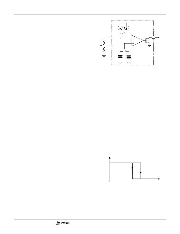
�FIGURE� 7.� CIRCUITRY� ASSOCIATED� WITH� THE� THERMAL�
�THROTTLING� FEATURE�
�Figure� 7� shows� the� circuitry� associated� with� the� thermal�
�throttling� feature� of� the� ISL6261A.� At� low� temperature,� SW1�
�is� on� and� SW2� connects� to� the� 1.20V� side.� The� total� current�
�going� into� the� NTC� pin� is� 60μA.� The� voltage� on� the� NTC� pin�
�is� higher� than� 1.20V� threshold� voltage� and� the� comparator�
�output� is� low.� VR_TT#� is� pulled� up� high� by� an� external�
�resistor.� Temperature� increase� will� decrease� the� NTC�
�thermistor� resistance.� This� decreases� the� NTC� pin� voltage.�
�When� the� NTC� pin� voltage� drops� below� 1.2V,� the� comparator�
�output� goes� high� to� pull� VR_TT#� low,� signaling� a� thermal�
�throttle.� In� addition,� SW1� turns� off� and� SW2� connects� to�
�1.23V,� which� decreases� the� NTC� pin� current� by� 6uA� and�
�increases� the� threshold� voltage� by� 30mV.� The� VR_TT#�
�signal� can� be� used� by� the� system� to� change� the� CPU�
�operation� and� decrease� the� power� consumption.� As� the�
�temperature� drops,� the� NTC� pin� voltage� goes� up.� If� the� NTC�
�pin� voltage� exceeds� 1.23V,� VR_TT#� will� be� pulled� high.�
�Figure� 8� illustrates� the� temperature� hysteresis� feature� of�
�VR_TT#.� T� 1� and� T� 2� (T� 1� >T� 2� )� are� two� threshold� temperatures.�
�VR_TT#� goes� low� when� the� temperature� is� higher� than� T� 1�
�and� goes� high� when� the� temperature� is� lower� than� T� 2� .�
�VR_TT#�
�Logic_1�
�Logic_0�
�T� (� o� C)�
�FIGURE� 8.� VR_TT#� TEMPERATURE� HYSTERISIS�
�FN6354.3�
�November� 5,� 2009�
�相关PDF资料 |
PDF描述 |
|---|---|
| AISC-1008F-8R2G-T | INDUCTOR 8200NH 330MA 2% SMD |
| FMC15DRYI-S13 | CONN EDGECARD 30POS .100 EXTEND |
| ESC07DREF | CONN EDGECARD 14POS .100 EYELET |
| TC1304-VP0EMF | IC REG DL BUCK/LINEAR SYNC 10DFN |
| EMC07DREF | CONN EDGECARD 14POS .100 EXTEND |
相关代理商/技术参数 |
参数描述 |
|---|---|
| ISL6261AIRZ | 功能描述:DC/DC 开关控制器 ONE-PHS INT DC/DC BUCK CNTRLR IMVP-6 RoHS:否 制造商:Texas Instruments 输入电压:6 V to 100 V 开关频率: 输出电压:1.215 V to 80 V 输出电流:3.5 A 输出端数量:1 最大工作温度:+ 125 C 安装风格: 封装 / 箱体:CPAK |
| ISL6261AIRZ-T | 功能描述:DC/DC 开关控制器 ONE-PHS INT DC/DC BUCK CNTRLR IMVP-6 RoHS:否 制造商:Texas Instruments 输入电压:6 V to 100 V 开关频率: 输出电压:1.215 V to 80 V 输出电流:3.5 A 输出端数量:1 最大工作温度:+ 125 C 安装风格: 封装 / 箱体:CPAK |
| ISL6261CR7Z | 功能描述:IC CTRLR BUCK 1PHASE 48-VFQFN EP RoHS:是 类别:集成电路 (IC) >> PMIC - 稳压器 - 专用型 系列:- 标准包装:43 系列:- 应用:控制器,Intel VR11 输入电压:5 V ~ 12 V 输出数:1 输出电压:0.5 V ~ 1.6 V 工作温度:-40°C ~ 85°C 安装类型:表面贴装 封装/外壳:48-VFQFN 裸露焊盘 供应商设备封装:48-QFN(7x7) 包装:管件 |
| ISL6261CR7Z-T | 功能描述:IC CTRLR BUCK 1PHASE 48-VFQFN-EP RoHS:是 类别:集成电路 (IC) >> PMIC - 稳压器 - 专用型 系列:- 标准包装:43 系列:- 应用:控制器,Intel VR11 输入电压:5 V ~ 12 V 输出数:1 输出电压:0.5 V ~ 1.6 V 工作温度:-40°C ~ 85°C 安装类型:表面贴装 封装/外壳:48-VFQFN 裸露焊盘 供应商设备封装:48-QFN(7x7) 包装:管件 |
| ISL6261CRZ | 功能描述:IC CTRLR BUCK 1PHASE 40-VFQFN-EP RoHS:是 类别:集成电路 (IC) >> PMIC - 稳压器 - 专用型 系列:- 标准包装:43 系列:- 应用:控制器,Intel VR11 输入电压:5 V ~ 12 V 输出数:1 输出电压:0.5 V ~ 1.6 V 工作温度:-40°C ~ 85°C 安装类型:表面贴装 封装/外壳:48-VFQFN 裸露焊盘 供应商设备封装:48-QFN(7x7) 包装:管件 |
发布紧急采购,3分钟左右您将得到回复。