参数资料
| 型号: | ISL62883IRTZ-T |
| 厂商: | Intersil |
| 文件页数: | 27/37页 |
| 文件大小: | 0K |
| 描述: | IC REG PWM 3PHASE BUCK 40TQFN |
| 标准包装: | 6,000 |
| 应用: | 控制器,Intel IMVP-6.5? |
| 输入电压: | 5 V ~ 21 V |
| 输出数: | 1 |
| 输出电压: | 0.013 V ~ 1.5 V |
| 工作温度: | -40°C ~ 100°C |
| 安装类型: | 表面贴装 |
| 封装/外壳: | 40-WFQFN 裸露焊盘 |
| 供应商设备封装: | 40-TQFN-EP(5x5) |
| 包装: | 带卷 (TR) |
第1页第2页第3页第4页第5页第6页第7页第8页第9页第10页第11页第12页第13页第14页第15页第16页第17页第18页第19页第20页第21页第22页第23页第24页第25页第26页当前第27页第28页第29页第30页第31页第32页第33页第34页第35页第36页第37页
�� �
�
�ISL62883,� ISL62883B�
�TABLE� 5.� LAYOUT� CONSIDERATION� (Continued)�
�TABLE� 5.� LAYOUT� CONSIDERATION� (Continued)�
�PIN�
�14�
�15�
�NAME�
�ISUM-�
�ISUM+�
�LAYOUT� CONSIDERATION�
�Place� the� current� sensing� circuit� in� general�
�proximity� of� the� controller.�
�Place� C82� very� close� to� the� controller.�
�Place� NTC� thermistors� R42� next� to� Phase-1�
�inductor� (L1)� so� it� senses� the� inductor� temperature�
�correctly.�
�Each� phase� of� the� power� stage� sends� a� pair� of�
�VSUM+� and� VSUM-� signals� to� the� controller.� Run�
�these� two� signals� traces� in� parallel� fashion� with�
�decent� width� (>20mil).�
�IMPORTANT:� Sense� the� inductor� current� by� routing�
�the� sensing� circuit� to� the� inductor� pads.�
�Route� R63� and� R71� to� the� Phase-1� side� pad� of�
�PIN�
�25�
�26�
�27�
�28�
�29�
�NAME�
�VCCP�
�LGATE2�
�VSSP2�
�PHASE2�
�UGATE2�
�LAYOUT� CONSIDERATION�
�A� capacitor� (C22)� decouples� it� to� GND.� Place� it� in�
�close� proximity� of� the� controller.�
�Run� these� two� traces� in� parallel� fashion� with�
�decent� width� (>30mil).� Avoid� any� sensitive� analog�
�signal� trace� from� crossing� over� or� getting� close.�
�Recommend� routing� VSSP2� to� the� Phase-2� low-�
�side� MOSFET� (Q5� and� Q1)� source� pins� instead� of�
�general� power� ground� plane� for� better�
�performance.�
�Run� these� two� traces� in� parallel� fashion� with�
�decent� width� (>30mil).� Avoid� any� sensitive� analog�
�signal� trace� from� crossing� over� or� getting� close.�
�inductor� L1.� Route� R88� to� the� output� side� pad� of�
�inductor� L1.�
�Route� R65� and� R72� to� the� Phase-2� side� pad� of�
�Recommend� routing� PHASE2� trace� to� the� Phase-2�
�high-side� MOSFET� (Q4� and� Q10)� source� pins�
�instead� of� general� Phase-2� node� copper.�
�inductor� L2.� Route� R90� to� the� output� side� pad� of�
�inductor� L2.�
�Route� R67� and� R73� to� the� Phase-3� side� pad� of�
�inductor� L3.� Route� R92� to� the� output� side� pad� of�
�inductor� L3.�
�30�
�31~37�
�BOOT2�
�VID0~6�
�Use� decent� wide� trace� (>30mil).� Avoid� any�
�sensitive� analog� signal� trace� from� crossing� over� or�
�getting� close.�
�No� special� consideration.�
�If� possible.� Route� the� traces� on� a� different� layer�
�from� the� inductor� pad� layer� and� use� vias� to�
�connect� the� traces� to� the� center� of� the� pads.� If� no�
�38�
�39�
�VR_ON� No� special� consideration.�
�DPRSLPVR� No� special� consideration.�
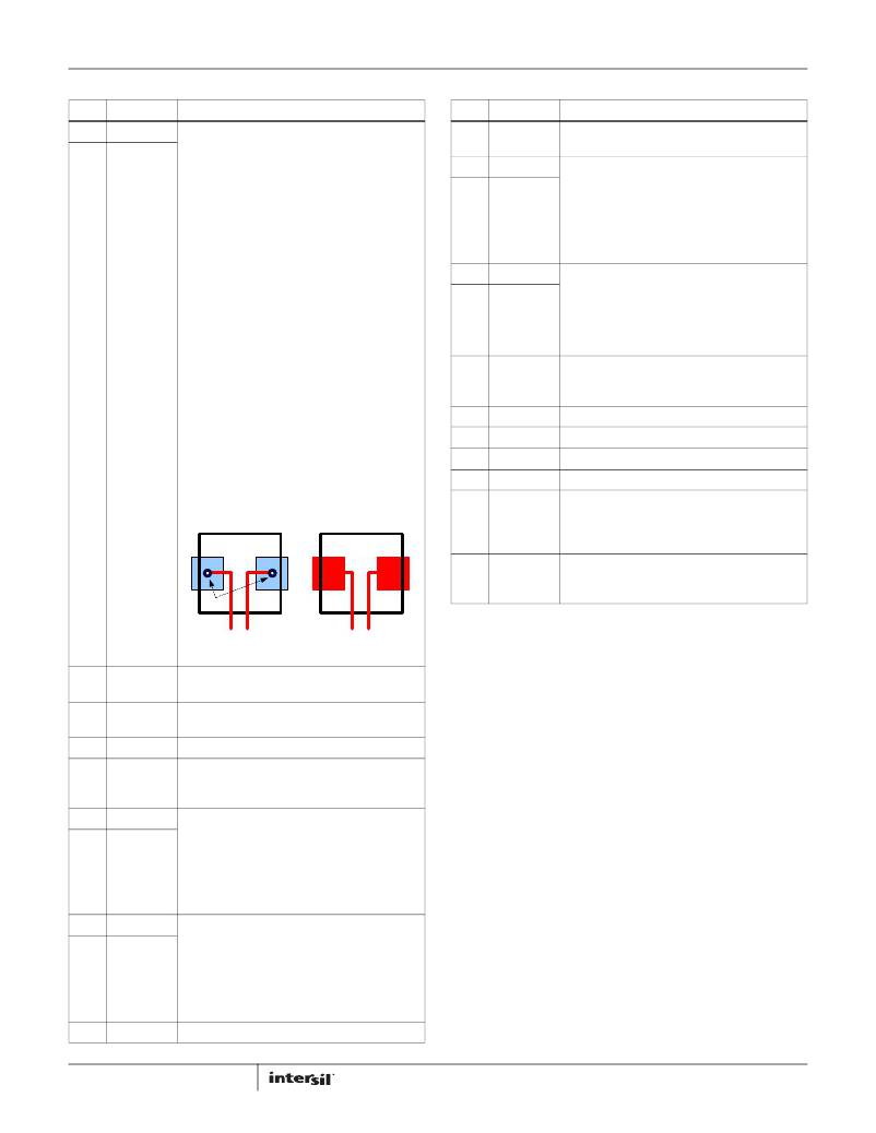
�via� is� allowed� on� the� pad,� consider� routing� the�
�traces� into� the� pads� from� the� inside� of� the�
�inductor.� The� following� drawings� show� the� two�
�preferred� ways� of� routing� current� sensing� traces.�
�40� CLK_EN#� No� special� consideration.�
�Other� Phase� Node� Minimize� phase� node� copper� area.� Don’t� let� the�
�phase� node� copper� overlap� with/getting� close� to�
�other� sensitive� traces.� Cut� the� power� ground� plane�
�Inductor�
�Inductor�
�Other�
�to� avoid� overlapping� with� phase� node� copper.�
�Minimize� the� loop� consisting� of� input� capacitor,�
�high-side� MOSFETs� and� low-side� MOSFETs� (e.g.:�
�Vias�
�Current-Sensing�
�Traces�
�Current-Sensing�
�Traces�
�C27,� C33,� Q2,� Q8,� Q3� and� Q9).�
�16�
�17�
�18�
�19�
�20�
�21�
�22�
�23�
�24�
�VDD�
�VIN�
�IMON�
�BOOT1�
�UGATE1�
�PHASE1�
�VSSP1�
�LGATE1�
�PWM3�
�A� capacitor� (C16)� decouples� it� to� GND.� Place� it� in�
�close� proximity� of� the� controller.�
�A� capacitor� (C17)� decouples� it� to� GND.� Place� it� in�
�close� proximity� of� the� controller.�
�Place� the� filter� capacitor� (C21)� close� to� the� CPU.�
�Use� decent� wide� trace� (>30mil).� Avoid� any�
�sensitive� analog� signal� trace� from� crossing� over� or�
�getting� close.�
�Run� these� two� traces� in� parallel� fashion� with�
�decent� width� (>30mil).� Avoid� any� sensitive� analog�
�signal� trace� from� crossing� over� or� getting� close.�
�Recommend� routing� PHASE1� trace� to� the� Phase-1�
�high-side� MOSFET� (Q2� and� Q8)� source� pins� instead�
�of� general�
�Phase-1� node� copper.�
�Run� these� two� traces� in� parallel� fashion� with�
�decent� width� (>30mil).� Avoid� any� sensitive� analog�
�signal� trace� from� crossing� over� or� getting� close.�
�Recommend� routing� VSSP1� to� the� Phase-1� low-�
�side� MOSFET� (Q3� and� Q9)� source� pins� instead� of�
�general� power� ground� plane� for� better�
�performance.�
�No� special� consideration.�
�27�
�FN6891.4�
�June� 21,� 2011�
�相关PDF资料 |
PDF描述 |
|---|---|
| 2512-153K | INDUCTOR POWER 15UH MOLDED SMD |
| X40021V14I-AT1 | IC VOLTAGE MONITOR DUAL 14-TSSOP |
| ISL62883HRTZ-T | IC REG PWM 3PHASE BUCK 40TQFN |
| RCM22DTBD-S189 | CONN EDGECARD 44POS R/A .156 SLD |
| RMC17DRSD-S273 | CONN EDGECARD 34POS DIP .100 SLD |
相关代理商/技术参数 |
参数描述 |
|---|---|
| ISL62884C | 制造商:INTERSIL 制造商全称:Intersil Corporation 功能描述:Single-Phase PWM Regulator for IMVP-6a?¢ Mobile CPUs |
| ISL62884CEVAL2Z | 功能描述:EVAL BOARD FOR ISL62884C RoHS:是 类别:编程器,开发系统 >> 评估板 - DC/DC 与 AC/DC(离线)SMPS 系列:- 产品培训模块:Obsolescence Mitigation Program 标准包装:1 系列:True Shutdown™ 主要目的:DC/DC,步升 输出及类型:1,非隔离 功率 - 输出:- 输出电压:- 电流 - 输出:1A 输入电压:2.5 V ~ 5.5 V 稳压器拓扑结构:升压 频率 - 开关:3MHz 板类型:完全填充 已供物品:板 已用 IC / 零件:MAX8969 |
| ISL62884CHRTZ | 功能描述:直流/直流开关调节器 1-PHS PWM BUCKG FOR MICROPROC PWR SUPPLY RoHS:否 制造商:International Rectifier 最大输入电压:21 V 开关频率:1.5 MHz 输出电压:0.5 V to 0.86 V 输出电流:4 A 输出端数量: 最大工作温度: 安装风格:SMD/SMT 封装 / 箱体:PQFN 4 x 5 |
| ISL62884CHRTZ-T | 功能描述:直流/直流开关调节器 1-PHS PWM BUCKG FOR MICROPROC PWR SUPPLY RoHS:否 制造商:International Rectifier 最大输入电压:21 V 开关频率:1.5 MHz 输出电压:0.5 V to 0.86 V 输出电流:4 A 输出端数量: 最大工作温度: 安装风格:SMD/SMT 封装 / 箱体:PQFN 4 x 5 |
| ISL62884CIRTZ | 功能描述:直流/直流开关调节器 1-PHS PWM BUCKG FOR MICROPROC PWR SUPPLY RoHS:否 制造商:International Rectifier 最大输入电压:21 V 开关频率:1.5 MHz 输出电压:0.5 V to 0.86 V 输出电流:4 A 输出端数量: 最大工作温度: 安装风格:SMD/SMT 封装 / 箱体:PQFN 4 x 5 |
发布紧急采购,3分钟左右您将得到回复。