- 您现在的位置:买卖IC网 > PDF目录20665 > ISL6425EVAL2 (Intersil)EVAL BOARD 2 FOR ISL6425 PDF资料下载
参数资料
| 型号: | ISL6425EVAL2 |
| 厂商: | Intersil |
| 文件页数: | 9/12页 |
| 文件大小: | 0K |
| 描述: | EVAL BOARD 2 FOR ISL6425 |
| 标准包装: | 1 |
| 系列: | * |
�� �
�
�ISL6425�
�Transmission� Without� Acknowledge�
�SDA�
�SCL�
�Avoiding� detection� of� the� acknowledgement,� the�
�microprocessor� can� use� a� simpler� transmission;� it� waits� one�
�clock� without� checking� the� slave� acknowledging,� and� sends�
�the� new� data.�
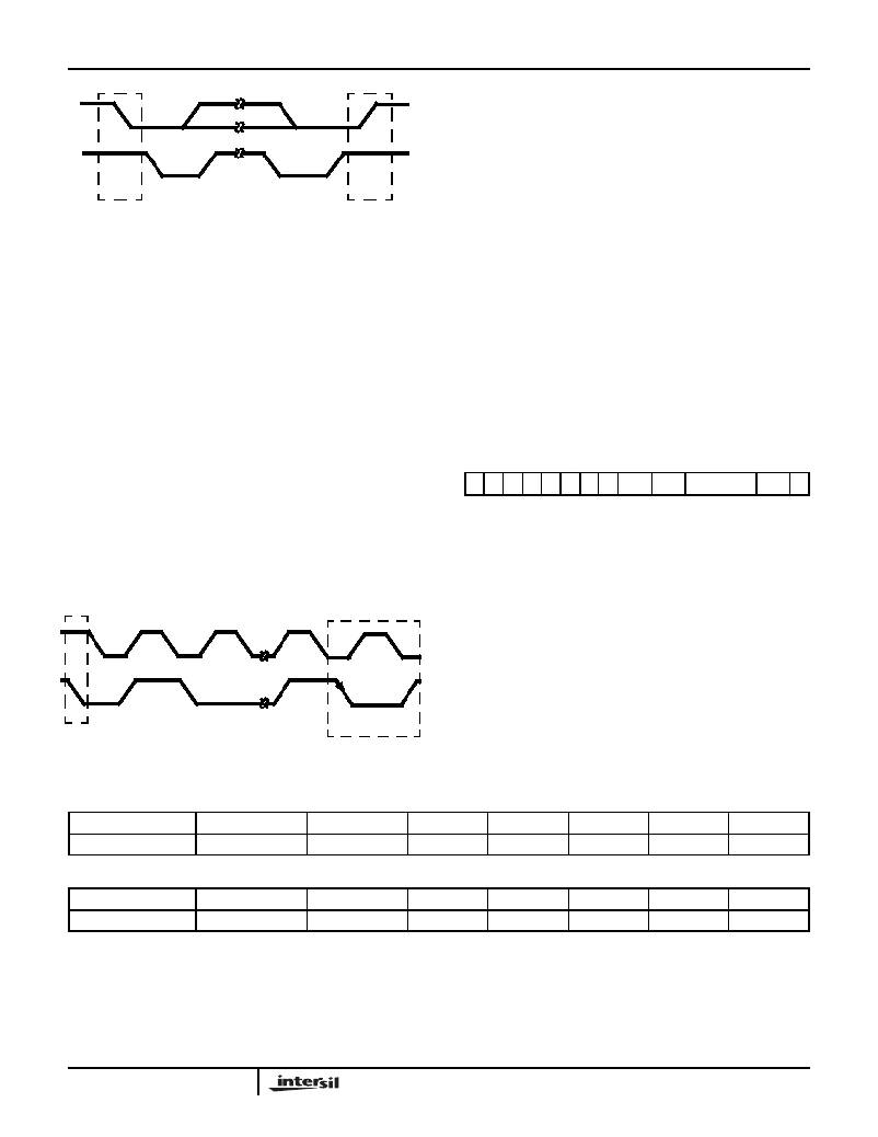
�S�
�START�
�CONDITION�
�P�
�STOP�
�CONDITION�
�This� approach,� though,� is� less� protected� from� error� and�
�decreases� the� noise� immunity.�
�FIGURE� 2.� START� AND� STOP� WAVEFORMS�
�Byte� Format�
�Every� byte� put� on� the� SDA� line� must� be� 8� bits� long.� The� number�
�of� bytes� that� can� be� transmitted� per� transfer� is� unrestricted.�
�Each� byte� has� to� be� followed� by� an� acknowledge� bit.� Data� is�
�transferred� with� the� most� significant� bit� first� (MSB).�
�Acknowledge�
�The� master� (microprocessor)� puts� a� resistive� HIGH� level� on�
�the� SDA� line� during� the� acknowledge� clock� pulse� (Figure� 3).�
�The� peripheral� that� acknowledges� has� to� pull� down� (LOW)�
�the� SDA� line� during� the� acknowledge� clock� pulse,� so� that� the�
�ISL6425� Software� Description�
�Interface� Protocol�
�The� interface� protocol� is� comprised� of� the� following,� as�
�shown� below� in� Table� 2:�
�?� A� start� condition� (S)�
�?� A� chip� address� byte� (MSB� on� left;� the� LSB� bit� determines�
�read� (1)� or� write� (0)� transmission)� (the� assigned� I� 2� C� slave�
�address� for� the� ISL6425� is� 0001� 00XX)�
�?� A� sequence� of� data� (1� byte� +� Acknowledge)�
�?� A� stop� condition� (P)�
�SDA� line� is� stable� LOW� during� this� clock� pulse.� (Of� course,�
�set-up� and� hold� times� must� also� be� taken� into� account.)�
�S�
�0�
�0�
�0�
�TABLE� 2.� INTERFACE� PROTOCOL�
�1� 0� 0� 0� R/W� ACK� Data� (8� bits)� ACK� P�
�The� peripheral� which� has� been� addressed� has� to� generate�
�an� acknowledge� after� the� reception� of� each� byte,� otherwise�
�the� SDA� line� remains� at� the� HIGH� level� during� the� ninth�
�clock� pulse� time.� In� this� case,� the� master� transmitter� can�
�generate� the� STOP� information� in� order� to� abort� the� transfer.�
�The� ISL6425� will� not� generate� the� acknowledge� if� the�
�POWER� OK� signal� from� the� UVLO� is� LOW.�
�SCL�
�Transmitted� Data� (� I� 2� C� bus� WRITE� mode)�
�When� the� R/W� bit� in� the� chip� is� set� to� 0,� the� main�
�microprocessor� can� write� on� the� system� register� (SR1)� of� the�
�ISL6425� via� I� 2� C� bus.� These� will� be� written� by� the�
�microprocessor� as� shown� below.�
�1�
�2�
�8�
�9�
�SDA�
�MSB�
�START�
�ACKNOWLEDGE�
�FROM� SLAVE�
�FIGURE� 3.� ACKNOWLEDGE� ON� THE� I� 2� C� BUS�
�TABLE� 3.� SYSTEM� REGISTER� 1� (SR1)�
�R,� W�
�SR1�
�R,� W�
�DCL�
�R,� W�
�X�
�R,� W�
�ENT1�
�R,� W�
�LLC1�
�R,� W�
�VSEL1�
�R,� W�
�EN1�
�R�
�OLF1�
�TABLE� 4.� SYSTEM� REGISTER� 2� (SR2)�
�R,� W�
�SR2�
�R,� W�
�X�
�R,� W�
�X�
�R,� W�
�X�
�R,� W�
�X�
�R,� W�
�EN2�
�R�
�OTF�
�R�
�X�
�System� Register� Format�
�?� R,� W� =� Read� and� Write� bit�
�?� R� =� Read-only� bit�
�All� bits� reset� to� 0� at� Power-On�
�9�
�FN9176.1�
�February� 8,� 2005�
�相关PDF资料 |
PDF描述 |
|---|---|
| ISL59532IK-EVAL | EVAL BOARD FOR ISL59532 |
| TC1304-VP0EMFTR | IC REG DL BUCK/LINEAR SYNC 10DFN |
| AISC-1008F-100G-T | INDUCTOR 10000NH 300MA 2% SMD |
| ISL6261AEVAL2Z | EVAL BOARD 2 FOR ISL6261A |
| AISC-1008F-8R2G-T | INDUCTOR 8200NH 330MA 2% SMD |
相关代理商/技术参数 |
参数描述 |
|---|---|
| ISL6426CB | 制造商:Rochester Electronics LLC 功能描述:- Bulk |
| ISL6426CR | 制造商:Rochester Electronics LLC 功能描述:- Bulk 制造商:Intersil Corporation 功能描述: |
| ISL6426CV | 制造商:Rochester Electronics LLC 功能描述:- Bulk 制造商:Intersil Corporation 功能描述: |
| ISL6426IB | 制造商:Rochester Electronics LLC 功能描述:- Bulk |
| ISL6426IB-T | 制造商:Rochester Electronics LLC 功能描述:- Tape and Reel |
发布紧急采购,3分钟左右您将得到回复。