- 您现在的位置:买卖IC网 > PDF目录15194 > ISL6439IRZ-T (Intersil)IC REG CTRLR BUCK PWM VM 16-QFN PDF资料下载
参数资料
| 型号: | ISL6439IRZ-T |
| 厂商: | Intersil |
| 文件页数: | 7/15页 |
| 文件大小: | 0K |
| 描述: | IC REG CTRLR BUCK PWM VM 16-QFN |
| 标准包装: | 6,000 |
| PWM 型: | 电压模式 |
| 输出数: | 1 |
| 频率 - 最大: | 340kHz |
| 占空比: | 100% |
| 电源电压: | 3.3 V ~ 5 V |
| 降压: | 是 |
| 升压: | 无 |
| 回扫: | 无 |
| 反相: | 无 |
| 倍增器: | 无 |
| 除法器: | 无 |
| Cuk: | 无 |
| 隔离: | 无 |
| 工作温度: | -40°C ~ 85°C |
| 封装/外壳: | 16-VQFN 裸露焊盘 |
| 包装: | 带卷 (TR) |
�� �
�
�ISL6439,� ISL6439A�
�CT1� and� CT2�
�These� pins� are� the� connections� for� the� external� charge�
�pump� capacitor.� A� minimum� of� a� 0.1� μ� F� ceramic� capacitor� is�
�recommended� for� proper� operation� of� the� IC.�
�CPVOUT�
�This� pin� represents� the� output� of� the� charge� pump.� The�
�voltage� at� this� pin� is� the� bias� voltage� for� the� IC.� Connect� a�
�decoupling� capacitor� from� this� pin� to� ground.� The� value� of�
�the� decoupling� capacitor� should� be� at� least� 10x� the� value� of�
�the� charge� pump� capacitor.� This� pin� may� be� tied� to� the�
�bootstrap� circuit� as� the� source� for� creating� the� BOOT�
�voltage.�
�CPGND�
�This� pin� represents� the� signal� and� power� ground� for� the�
�charge� pump.� Tie� this� pin� to� the� ground� island/plane� through�
�the� lowest� impedance� connection� available.�
�Functional� Description�
�Initialization�
�The� ISL6439� automatically� initializes� upon� receipt� of� power.�
�Special� sequencing� of� the� input� supplies� is� not� necessary.�
�The� Power-On� Reset� (POR)� function� continually� monitors� the�
�the� output� voltage� of� the� charge� pump.� During� POR,� the� charge�
�pump� operates� on� a� free� running� oscillator.� Once� the� POR� level�
�is� reached,� the� charge� pump� oscillator� is� synched� to� the� PWM�
�oscillator.� The� POR� function� also� initiates� the� soft-start�
�operation� after� the� charge� pump� output� voltage� exceeds� its�
�POR� threshold.�
�Soft-Start�
�The� POR� function� initiates� the� digital� soft-start� sequence.� The�
�PWM� error� amplifier� reference� is� clamped� to� a� level�
�proportional� to� the� soft-start� voltage.� As� the� soft-start� voltage�
�slews� up,� the� PWM� comparator� generates� PHASE� pulses� of�
�increasing� width� that� charge� the� output� capacitor(s).� This�
�method� provides� a� rapid� and� controlled� output� voltage� rise.� The�
�soft� start� sequence� typically� takes� about� 6.5ms.�
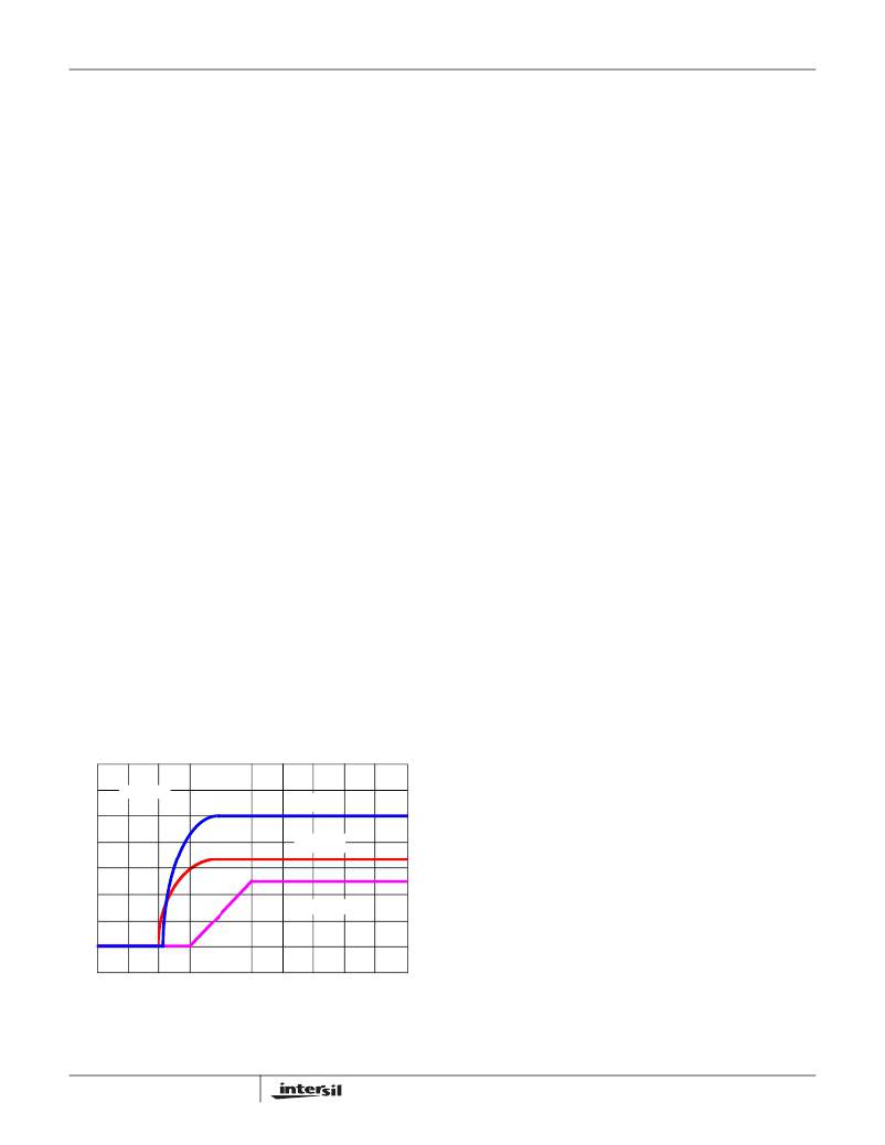
�Figure� 1� shows� the� soft-start� sequence� for� a� typical� application.�
�At� t0,� the� +3.3V� VCC� voltage� starts� to� ramp.� At� time� t1,� the�
�Charge� Pump� begins� operation� and� the� +5V� CPVOUT� IC� bias�
�voltage� starts� to� ramp� up.� Once� the� voltage� on� CPVOUT�
�crosses� the� POR� threshold� at� time� t2,� the� output� begins� the�
�soft-start� sequence.� The� triangle� waveform� from� the� PWM�
�oscillator� is� compared� to� the� rising� error� amplifier� output�
�voltage.� As� the� error� amplifier� voltage� increases,� the� pulse-�
�width� on� the� UGATE� pin� increases� to� reach� the� steady-state�
�duty� cycle� at� time� t3.�
�Shoot-Through� Protection�
�A� shoot-through� condition� occurs� when� both� the� upper�
�MOSFET� and� lower� MOSFET� are� turned� on� simultaneously,�
�effectively� shorting� the� input� voltage� to� ground.� To� protect�
�the� regulator� from� a� shoot-through� condition,� the� ISL6439�
�incorporates� specialized� circuitry� which� insures� that� the�
�complementary� MOSFETs� are� not� ON� simultaneously.�
�The� adaptive� shoot-through� protection� utilized� by� the�
�ISL6439� looks� at� the� lower� gate� drive� pin,� LGATE,� and� the�
�upper� gate� drive� pin,� UGATE,� to� determine� whether� a�
�MOSFET� is� ON� or� OFF.� If� the� voltage� from� UGATE� or� from�
�LGATE� to� GND� is� less� than� 0.8V,� then� the� respective�
�MOSFET� is� defined� as� being� OFF� and� the� complementary�
�MOSFET� is� turned� ON.� This� method� of� shoot-through�
�protection� allows� the� regulator� to� sink� or� source� current.�
�Since� the� voltage� of� the� lower� MOSFET� gate� and� the� upper�
�MOSFET� gate� are� being� measured� to� determine� the� state� of�
�the� MOSFET,� the� designer� is� encouraged� to� consider� the�
�repercussions� of� introducing� external� components� between�
�the� gate� drivers� and� their� respective� MOSFET� gates� before�
�actually� implementing� such� measures.� Doing� so� may�
�interfere� with� the� shoot-through� protection.�
�Output� Voltage� Selection�
�The� output� voltage� can� be� programmed� to� any� level� between�
�V� IN� and� the� internal� reference,� 0.8V.� An� external� resistor�
�divider� is� used� to� scale� the� output� voltage� relative� to� the�
�reference� voltage� and� feed� it� back� to� the� inverting� input� of�
�the� error� amplifier,� see� Figure� 2.� However,� since� the� value� of�
�(1V/DIV)�
�CPVOUT� (5V)�
�R1� affects� the� values� of� the� rest� of� the� compensation�
�components,� it� is� advisable� to� keep� its� value� less� than� 5k� Ω� .�
�R4� can� be� calculated� based� on� Equation� 2:�
�R1� � 0.8V�
�VCC (3.3V)�
�R4� =� --------------------------------------�
�V� OUT1� –� 0.8V�
�(EQ.� 2)�
�0V�
�V� OUT� (2.50V)�
�If� the� output� voltage� desired� is� 0.8V,� simply� route� the� output�
�back� to� the� FB� pin� through� R1,� but� do� not� populate� R4.�
�Overcurrent� Protection�
�The� overcurrent� function� protects� the� converter� from� a� shorted�
�T0�
�T1�
�T2�
�T3�
�TIME�
�output� by� using� the� upper� MOSFET� on-resistance,� r� DS(ON)� ,� to�
�monitor� the� current.� This� method� enhances� the� converter’s�
�FIGURE� 1.� SOFT-START� INTERVAL�
�7�
�efficiency� and� reduces� cost� by� eliminating� a� current� sensing�
�resistor.�
�FN9057.5�
�November� 5,� 2008�
�相关PDF资料 |
PDF描述 |
|---|---|
| RSC12DRES-S93 | CONN EDGECARD 24POS .100 EYELET |
| ISL6439AIRZ-T | IC REG CTRLR BUCK PWM VM 16-QFN |
| ISL6545CRZ-TS2694 | IC REG CTRLR BUCK PWM VM 10-DFN |
| ISL88002IE26Z-TK | IC VOLT SUPERVISOR 2.63V SC-70 |
| ISL6545CRZ-T | IC REG CTRLR BUCK PWM VM 10-DFN |
相关代理商/技术参数 |
参数描述 |
|---|---|
| ISL6440ACB WAF | 制造商:Harris Corporation 功能描述: |
| ISL6440ACB-T | 制造商:Rochester Electronics LLC 功能描述:- Bulk |
| ISL6440EVAL1 | 制造商:Intersil Corporation 功能描述:EVAL BD FOR ISL6440 - Bulk |
| ISL6440EVAL1Z | 功能描述:EVALUATION BOARD FOR ISL6440 RoHS:是 类别:编程器,开发系统 >> 评估板 - DC/DC 与 AC/DC(离线)SMPS 系列:- 产品培训模块:Obsolescence Mitigation Program 标准包装:1 系列:True Shutdown™ 主要目的:DC/DC,步升 输出及类型:1,非隔离 功率 - 输出:- 输出电压:- 电流 - 输出:1A 输入电压:2.5 V ~ 5.5 V 稳压器拓扑结构:升压 频率 - 开关:3MHz 板类型:完全填充 已供物品:板 已用 IC / 零件:MAX8969 |
| ISL6440IA | 功能描述:IC REG CTRLR BUCK PWM CM 24-QSOP RoHS:否 类别:集成电路 (IC) >> PMIC - 稳压器 - DC DC 切换控制器 系列:- 标准包装:4,000 系列:- PWM 型:电压模式 输出数:1 频率 - 最大:1.5MHz 占空比:66.7% 电源电压:4.75 V ~ 5.25 V 降压:是 升压:无 回扫:无 反相:无 倍增器:无 除法器:无 Cuk:无 隔离:无 工作温度:-40°C ~ 85°C 封装/外壳:40-VFQFN 裸露焊盘 包装:带卷 (TR) |
发布紧急采购,3分钟左右您将得到回复。